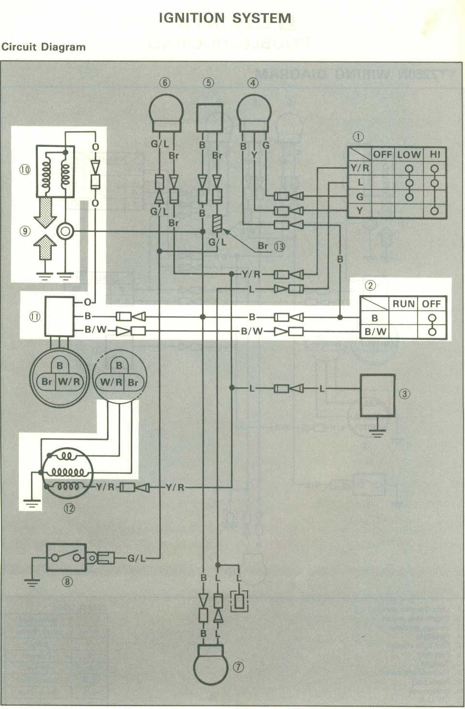
Are you looking for information on Yamaha Bear Tracker 250 Wiring Diagram? Understanding the wiring diagram for your Yamaha Bear Tracker 250 is crucial for proper maintenance and troubleshooting of the electrical system.
Why Yamaha Bear Tracker 250 Wiring Diagrams are essential
- Help in identifying components and their connections
- Aid in understanding the electrical system layout
- Assist in diagnosing electrical issues
- Provide guidance for repairs and modifications
How to read and interpret Yamaha Bear Tracker 250 Wiring Diagrams effectively
When reading a wiring diagram for your Yamaha Bear Tracker 250, it’s important to understand the symbols and color codes used. Here are some tips to help you interpret the diagram:
- Identify the key components such as batteries, switches, connectors, and wires
- Follow the flow of current from the power source to the various components
- Pay attention to how components are connected and the direction of current flow
Using Yamaha Bear Tracker 250 Wiring Diagrams for troubleshooting electrical problems
Wiring diagrams are invaluable tools for troubleshooting electrical issues in your Yamaha Bear Tracker 250. Here’s how you can use them effectively:
- Locate the specific circuit or component that is causing the problem
- Trace the wiring to identify any breaks, shorts, or loose connections
- Refer to the diagram to understand how the circuit is supposed to work
- Use a multimeter to test for continuity, voltage, and resistance
Importance of safety when working with electrical systems
When working with electrical systems and using wiring diagrams, safety should be your top priority. Here are some safety tips and best practices to follow:
- Always disconnect the battery before working on the electrical system
- Use insulated tools to prevent electrical shocks
- Avoid working on the electrical system in wet or damp conditions
- Double-check your work to ensure all connections are secure and correct
Yamaha Bear Tracker 250 Wiring Diagram
Vera Wiring: Yamaha 250 Bear Tracker Wiring Diagram
Yamaha Bear Tracker 250 Wiring Diagram – Wiring Diagram Schematic

yamaha bear tracker 250 wiring diagram – Lace Hub

Yamaha Bear Tracker 250 Wiring Diagram Database

2000 yamaha bear tracker 250 wiring diagram

1999 yamaha bear tracker 250 wiring diagram
