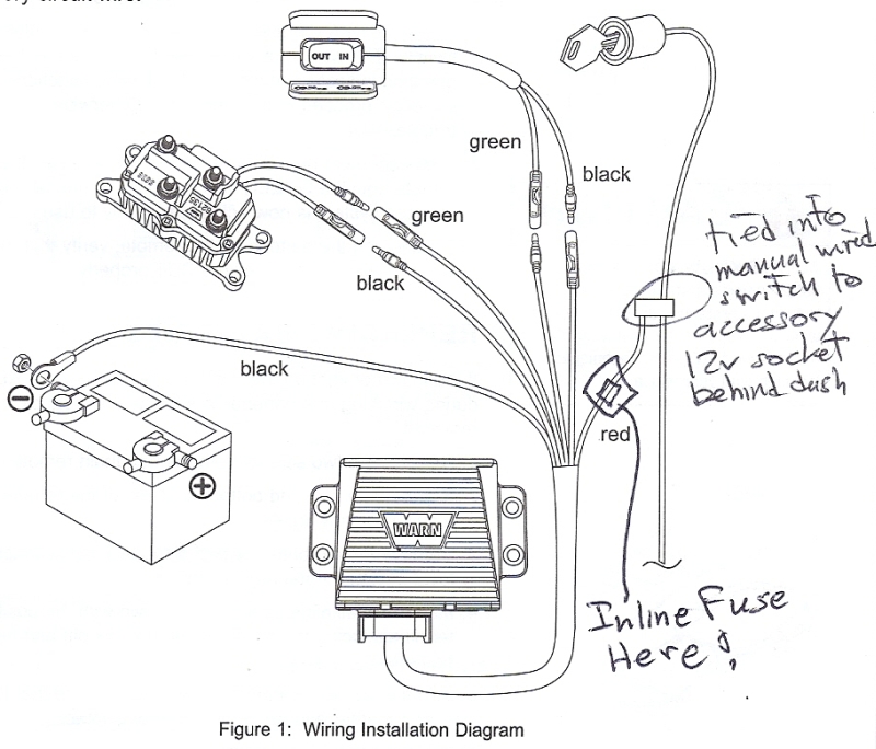
Wireless Remote Winch Wiring Diagrams are crucial tools for understanding the electrical connections and components of a winch system. These diagrams provide a visual representation of how the various wires are connected, allowing mechanics and DIY enthusiasts to troubleshoot issues, make repairs, or install new components with ease.
Importance of Wireless Remote Winch Wiring Diagrams
- Ensure proper installation of winch components
- Aid in troubleshooting electrical issues
- Prevent electrical shorts or malfunctions
Reading and Interpreting Wireless Remote Winch Wiring Diagrams
When looking at a wiring diagram for a wireless remote winch, it’s important to understand the symbols and color codes used to represent different components and wires. The key components to look for include the winch motor, solenoid, battery, and remote control receiver. By following the lines and connections in the diagram, you can easily trace the flow of electricity throughout the system.
Using Wireless Remote Winch Wiring Diagrams for Troubleshooting
Wireless Remote Winch Wiring Diagrams can be invaluable when diagnosing electrical problems with a winch system. By comparing the diagram to the actual wiring setup, you can identify any faulty connections, damaged wires, or malfunctioning components. This can save time and effort in pinpointing the root cause of the issue and making the necessary repairs.
Safety Tips for Working with Wireless Remote Winch Wiring Diagrams
- Always disconnect the power source before working on the electrical system
- Use insulated tools to avoid the risk of electric shock
- Double-check all connections and wiring before testing the system
- Follow manufacturer instructions and guidelines for proper installation and maintenance
Wireless Remote Winch Wiring Diagram
Wireless Winch Remote Wiring Diagram – Wiring Site Resource

Wireless Winch Remote Control. 12v, Twin Handset | Winchmax

Badland 2500 Winch Wireless Remote Wiring Diagram

How to wire up electric winch wireless controller remote 4×4 4wd truck

12volt Wireless Winch Remote Wiring Diagram – Wiring Diagram Pictures

#KFI-WRC Wireless Remote Kit – KFI ATV Winch, Mounts and Accessories
