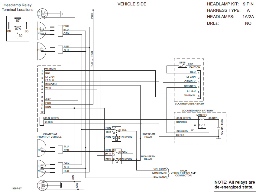
Western Plow Control Wiring Diagrams are essential tools for understanding the electrical systems of Western plows. These diagrams provide detailed information on how the various components of the plow control system are connected and how they interact with each other.
Why Western Plow Control Wiring Diagrams are Essential
- Helps in understanding the wiring configuration of the plow control system.
- Aids in troubleshooting electrical issues effectively.
- Ensures proper installation and maintenance of the plow control system.
Reading and Interpreting Western Plow Control Wiring Diagrams
When reading a Western Plow Control Wiring Diagram, it is important to understand the symbols and color codes used. The key components to focus on include the power source, control module, solenoid valves, and motor. By studying the diagram carefully, you can determine how the electrical signals flow through the system and identify any potential issues.
Using Western Plow Control Wiring Diagrams for Troubleshooting
Western Plow Control Wiring Diagrams are invaluable for troubleshooting electrical problems in the plow system. By referencing the diagram, you can trace the flow of electricity and pinpoint the source of the issue. This can help you make accurate repairs and ensure the system is functioning properly.
Importance of Safety
Working with electrical systems can be dangerous if proper precautions are not taken. When using Western Plow Control Wiring Diagrams, it is important to follow these safety tips:
- Always disconnect the power source before working on the system.
- Use insulated tools to prevent electric shocks.
- Avoid working on the system in wet or damp conditions.
- Double-check your work to ensure all connections are secure before restoring power.
Western Plow Control Wiring Diagram
Western Plow Controller Wiring Diagram

unimount western plow wiring diagram – SummerMathieu

western plow control wiring diagram – Green Lab

western plows wiring diagram

Western Plow 9 Pin Wiring Diagram – Green Lab

9 Pin Western Plow Wiring Diagram – Mary Circuit
