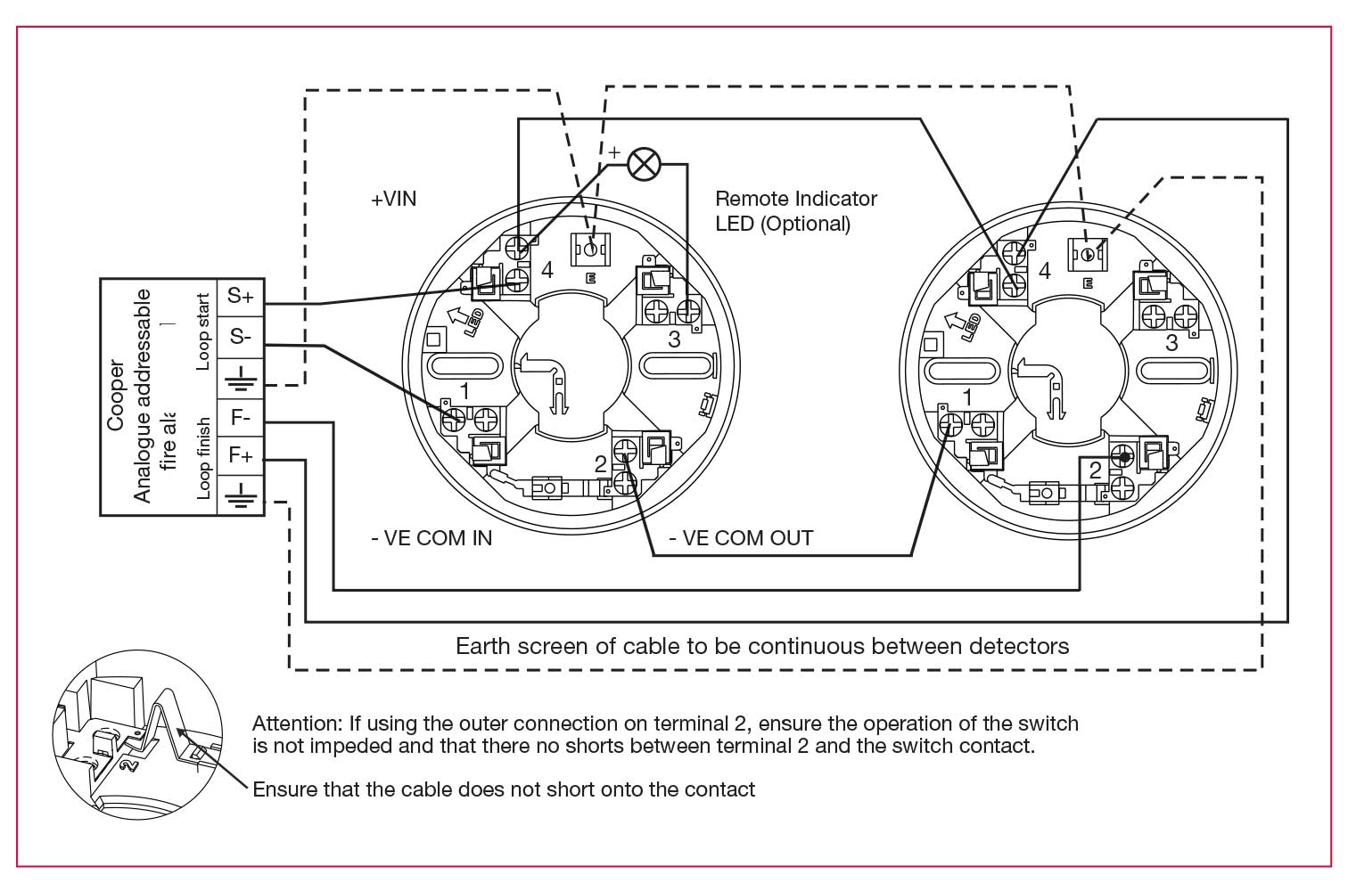
When it comes to ensuring the safety and functionality of a building’s fire alarm system, understanding the System Sensor Duct Detector Wiring Diagram is crucial. This diagram provides valuable information on how the duct detector is wired into the building’s electrical system, allowing for proper installation, maintenance, and troubleshooting.
Importance of System Sensor Duct Detector Wiring Diagram
System Sensor Duct Detector Wiring Diagrams are essential for the following reasons:
- Ensure proper installation of the duct detector
- Facilitate routine maintenance and repairs
- Aid in troubleshooting electrical issues
- Comply with building codes and regulations
Reading and Interpreting System Sensor Duct Detector Wiring Diagram
Reading and interpreting System Sensor Duct Detector Wiring Diagrams can be daunting for some, but with a basic understanding of electrical symbols and conventions, it becomes much easier. Here are some key tips:
- Identify the components and their corresponding symbols
- Follow the flow of the wiring diagram to understand the connections
- Pay attention to labels and color codes for wires
Using System Sensor Duct Detector Wiring Diagram for Troubleshooting
System Sensor Duct Detector Wiring Diagrams are invaluable when it comes to troubleshooting electrical problems. By following the wiring diagram, you can:
- Identify faulty connections or components
- Trace the path of electrical current to pinpoint the issue
- Ensure that all connections are secure and properly grounded
Safety Tips for Working with System Sensor Duct Detector Wiring Diagram
Working with electrical systems can be dangerous, so it’s important to prioritize safety at all times. Here are some safety tips to keep in mind:
- Always turn off the power before working on any electrical components
- Use insulated tools to prevent electric shocks
- Wear appropriate personal protective equipment, such as gloves and safety glasses
- Double-check all connections before restoring power to the system
System Sensor Duct Detector Wiring Diagram
System Sensor Duct Detector Dh400acdc Wiring Diagram – Wiring Diagram

Innovair Duct Detector Wiring Diagram – Wiring Diagram

System Sensor D4120 Wiring Diagram – Using A Manometer To Test Duct

How to Properly Wire a System Sensor Duct Detector

Sl 2000 Duct Detector Wiring

system sensor duct detector wiring diagram
