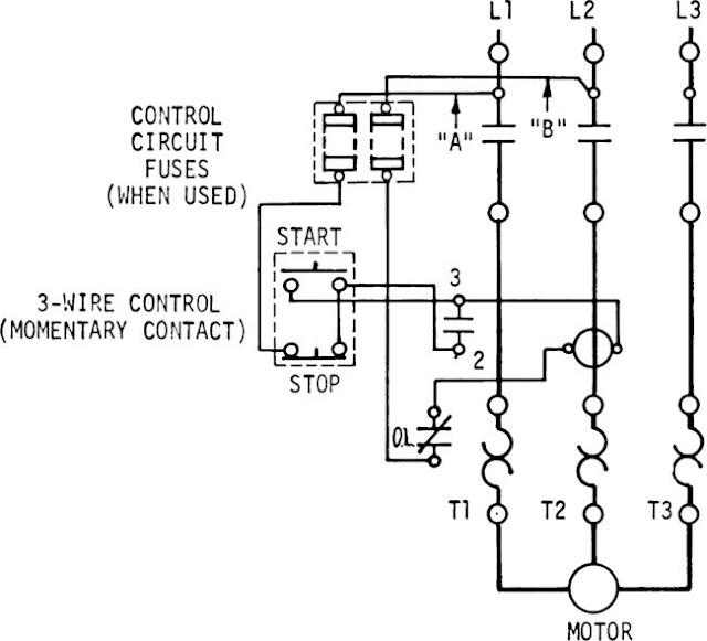
When it comes to understanding the intricacies of electrical systems in industrial settings, having a clear grasp of the Start Stop Station Wiring Diagram is crucial. This diagram serves as a visual representation of the wiring connections and components involved in the operation of a start-stop station, providing invaluable information for technicians and engineers.
Why Start Stop Station Wiring Diagrams are Essential
Start Stop Station Wiring Diagrams are essential for several reasons:
- They provide a detailed overview of the electrical connections involved in a start-stop station.
- They help in understanding the sequence of operation of the start-stop station.
- They assist in troubleshooting electrical issues that may arise during the operation of the station.
Reading and Interpreting Start Stop Station Wiring Diagrams
Reading and interpreting Start Stop Station Wiring Diagrams can be simplified by following these steps:
- Identify the components listed in the diagram.
- Follow the flow of the wiring connections from the power source to the components.
- Understand the symbols and abbreviations used in the diagram.
Using Start Stop Station Wiring Diagrams for Troubleshooting
Start Stop Station Wiring Diagrams are invaluable tools for troubleshooting electrical problems. By following the wiring connections and understanding the sequence of operation, technicians can pinpoint issues and make necessary repairs efficiently. Common troubleshooting steps include:
- Checking for loose connections or damaged wires.
- Testing components for continuity and proper functioning.
- Verifying the power supply to the start-stop station.
Importance of Safety
Working with electrical systems and wiring diagrams requires strict adherence to safety precautions to prevent accidents and injuries. Some essential safety tips include:
- Always de-energize the circuit before working on electrical components.
- Use insulated tools and personal protective equipment when handling electrical connections.
- Follow proper lockout/tagout procedures to ensure the circuit is safely isolated.
Start Stop Station Wiring Diagram
Start Stop Circuit – What They Are, Where They Are Used And How To Wire

The Essential Guide to Start-stop Diagram – RAYPCB

Wiring Diagram Start Stop Motor Control – a threewire startstop circuit

3 Phase Start Stop Wiring Diagram

Start-stop Circuits: Everything You Need To Know
Start Stop Station Schematic
