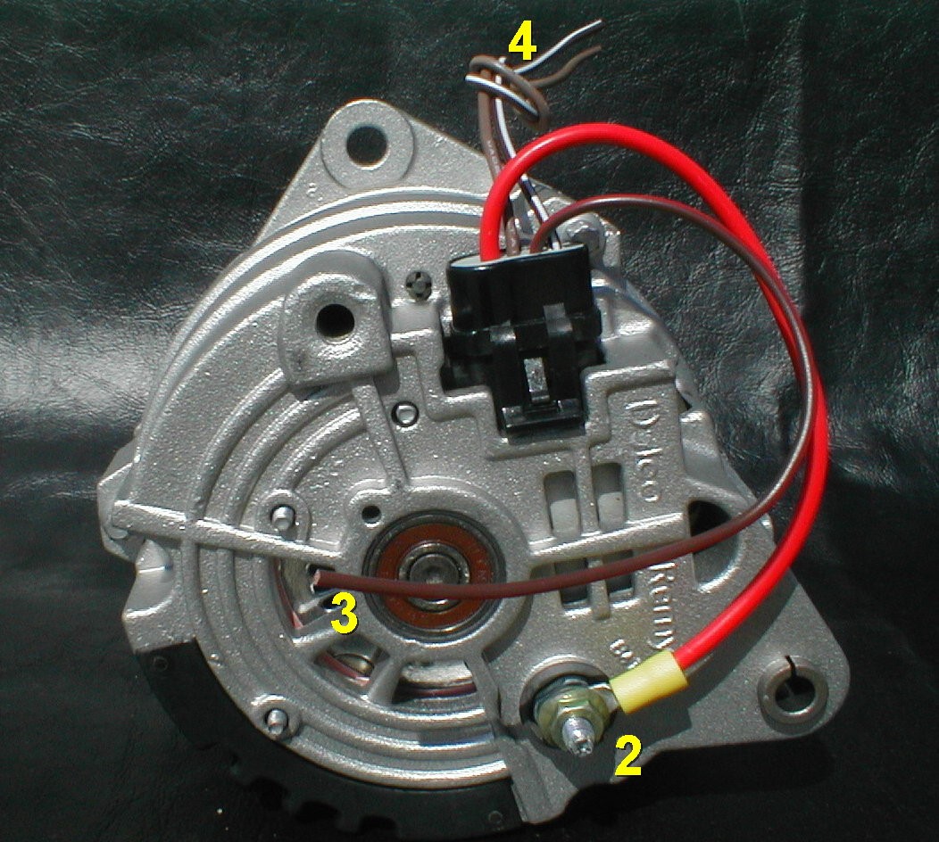
Single Wire Alternator Wiring Diagram
A Single Wire Alternator Wiring Diagram is a schematic representation of the electrical connections and components of a single wire alternator system. It provides a visual guide to help understand how the alternator is wired and how it functions within the vehicle’s electrical system.
Why Single Wire Alternator Wiring Diagrams are Essential
- Helps in understanding the electrical connections of the alternator system
- Aids in troubleshooting electrical problems
- Ensures proper installation and wiring of the alternator
- Provides a reference for future maintenance or repairs
Reading and Interpreting Single Wire Alternator Wiring Diagrams
- Identify the components and their corresponding symbols on the diagram
- Follow the flow of electrical connections from the alternator to the battery
- Understand the color codes and labels used in the diagram
- Refer to the key or legend for any symbols or abbreviations used
Using Single Wire Alternator Wiring Diagrams for Troubleshooting
- Locate the specific component or connection that may be causing the issue
- Check for continuity and proper voltage levels at different points in the circuit
- Compare the actual wiring with the diagram to identify any discrepancies
- Consult the wiring diagram to determine the correct troubleshooting steps to take
Importance of Safety
When working with electrical systems and using wiring diagrams, it is crucial to prioritize safety. Here are some safety tips and best practices:
- Always disconnect the battery before working on the electrical system
- Use insulated tools to prevent electrical shocks
- Avoid working on the wiring when the engine is running
- Double-check all connections before re-energizing the system
- If unsure, seek professional assistance to avoid accidents or damage to the vehicle
Single Wire Alternator Wiring Diagram
Wiring Diagram 1 Wire Alternator – Wiring Diagram and Schematics

Single Wire Alternator Wiring Diagram – Database – Faceitsalon.com
Gm Single Wire Alternator Wiring Diagram

10100: Installation Instructions for 1-Wire Alternators

One Wire Gm Alternator Wiring Diagram

Technical – Alternators/charging and 1 wire | The H.A.M.B.
