Reverse Camera Wiring Diagram
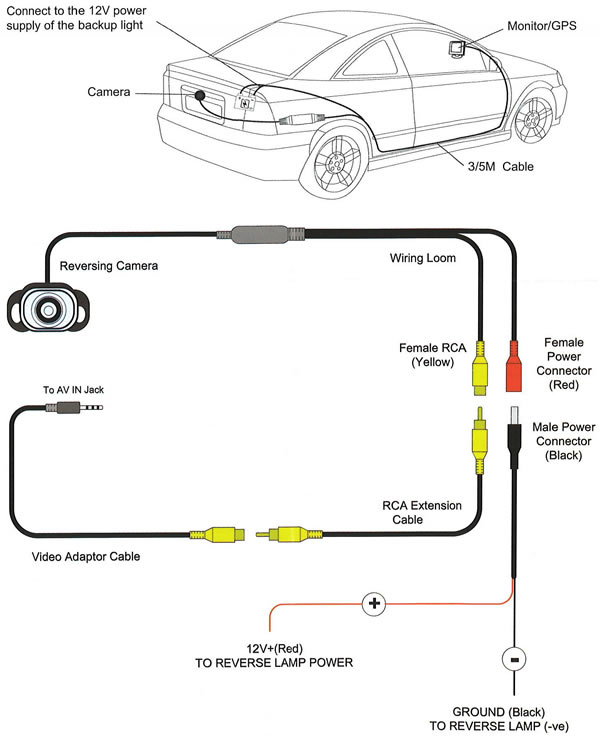
Reverse Camera Wiring Diagram is a crucial tool for anyone looking to install or troubleshoot a reverse camera system in their vehicle. This diagram provides a visual representation of the wiring connections needed to properly install the camera and ensure it functions correctly.
Why Reverse Camera Wiring Diagrams are Essential
- Helps ensure proper installation of the reverse camera system
- Aids in troubleshooting any issues with the camera or wiring
- Provides a clear guide for connecting the camera to the vehicle’s electrical system
How to Read and Interpret Reverse Camera Wiring Diagrams Effectively
When looking at a reverse camera wiring diagram, it’s important to pay attention to the following:
- Color coding of wires for easy identification
- Connection points for power, ground, and video signal
- Any additional components or connections required for the camera system
Using Reverse Camera Wiring Diagrams for Troubleshooting
Reverse camera wiring diagrams can also be used to troubleshoot any electrical problems with the camera system. By following the diagram and checking the connections, you can identify and fix any issues with the wiring, power supply, or camera itself.
Importance of Safety
When working with electrical systems and using wiring diagrams, it’s crucial to prioritize safety. Here are some tips to ensure a safe working environment:
- Always disconnect the vehicle’s battery before working on any electrical components
- Avoid working on electrical systems in wet or damp conditions
- Use insulated tools to prevent electric shock
- If you’re unsure about any part of the installation or troubleshooting process, seek help from a professional
Reverse Camera Wiring Diagram
Wireless Reversing Camera Wiring Diagram

The Ultimate Guide to Understanding the 5 Pin Reverse Camera Wiring Diagram

How to set up my reverse camera? – Pioneer

Kenwood Reverse Camera Wiring Diagram – Earthica
The Ultimate Guide to Understanding the 5 Pin Reverse Camera Wiring Diagram

The Ultimate Guide to Understanding the 5 Pin Reverse Camera Wiring Diagram
