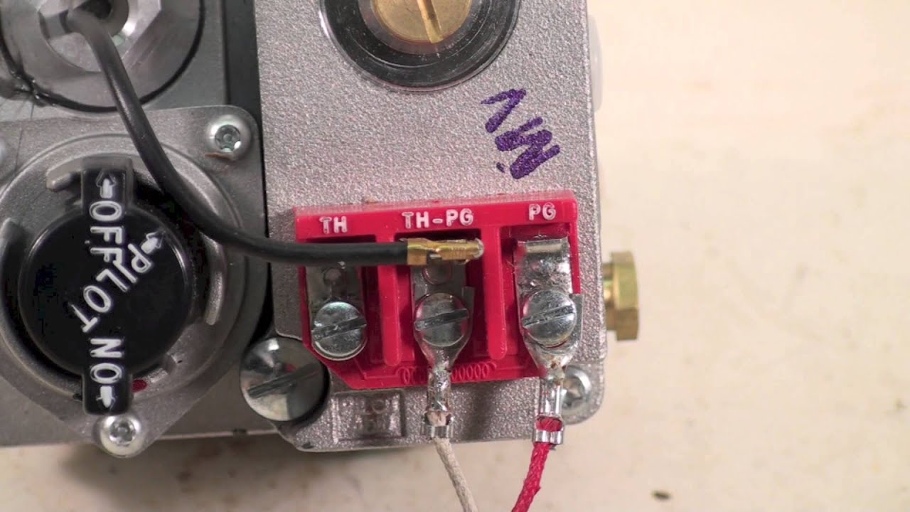
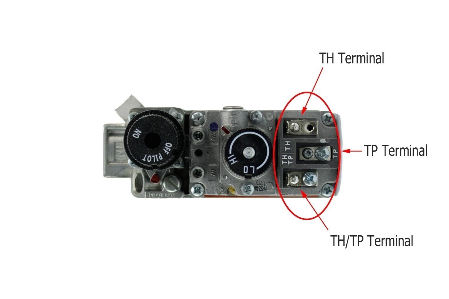
Millivolt gas valve wiring diagrams are an essential tool for any mechanic or technician working with gas appliances. These diagrams provide a detailed illustration of how the various components of a millivolt gas valve system are connected and powered. Understanding how to read and interpret these diagrams is crucial for troubleshooting electrical issues and ensuring the safe operation of gas appliances.
Why Millivolt Gas Valve Wiring Diagrams are Essential
- Provide a visual representation of the electrical connections in a millivolt gas valve system
- Help identify faulty components or wiring issues
- Aid in the installation and maintenance of gas appliances
- Ensure the safe operation of gas valves and prevent potential hazards
Reading and Interpreting Millivolt Gas Valve Wiring Diagrams
When looking at a millivolt gas valve wiring diagram, it’s important to pay attention to the following:
- Identify the various components such as the gas valve, thermocouple, pilot light, and thermostat
- Understand the symbols and color codes used in the diagram
- Follow the flow of electricity through the system to troubleshoot issues
Using Millivolt Gas Valve Wiring Diagrams for Troubleshooting
Millivolt gas valve wiring diagrams can be invaluable when trying to diagnose electrical problems. By following the wiring diagram and checking the connections, you can pinpoint the source of issues such as a malfunctioning gas valve, faulty thermocouple, or wiring defects. This can save time and effort in troubleshooting and repair.
Importance of Safety
Working with electrical systems, including using wiring diagrams, can pose various safety hazards if not done correctly. Here are some safety tips and best practices to keep in mind:
- Always turn off the power supply before working on any electrical components
- Use insulated tools and wear appropriate protective gear
- Avoid working on electrical systems in wet or damp conditions
- If unsure or inexperienced, seek the help of a qualified professional
Millivolt Gas Valve Wiring Diagram
Millivolt Gas Valve Wiring Diagram

Honeywell Millivolt Gas Valve Wiring Diagram For Your Needs

Honeywell Millivolt Gas Valve Wiring Diagram

White Mountain Hearth VFSURxx Ventless Double Sided Slope Glaze Burner

How to Properly Wire a Millivolt Gas Valve for Efficient Heating

How to Properly Wire a Millivolt Gas Valve for Efficient Heating
