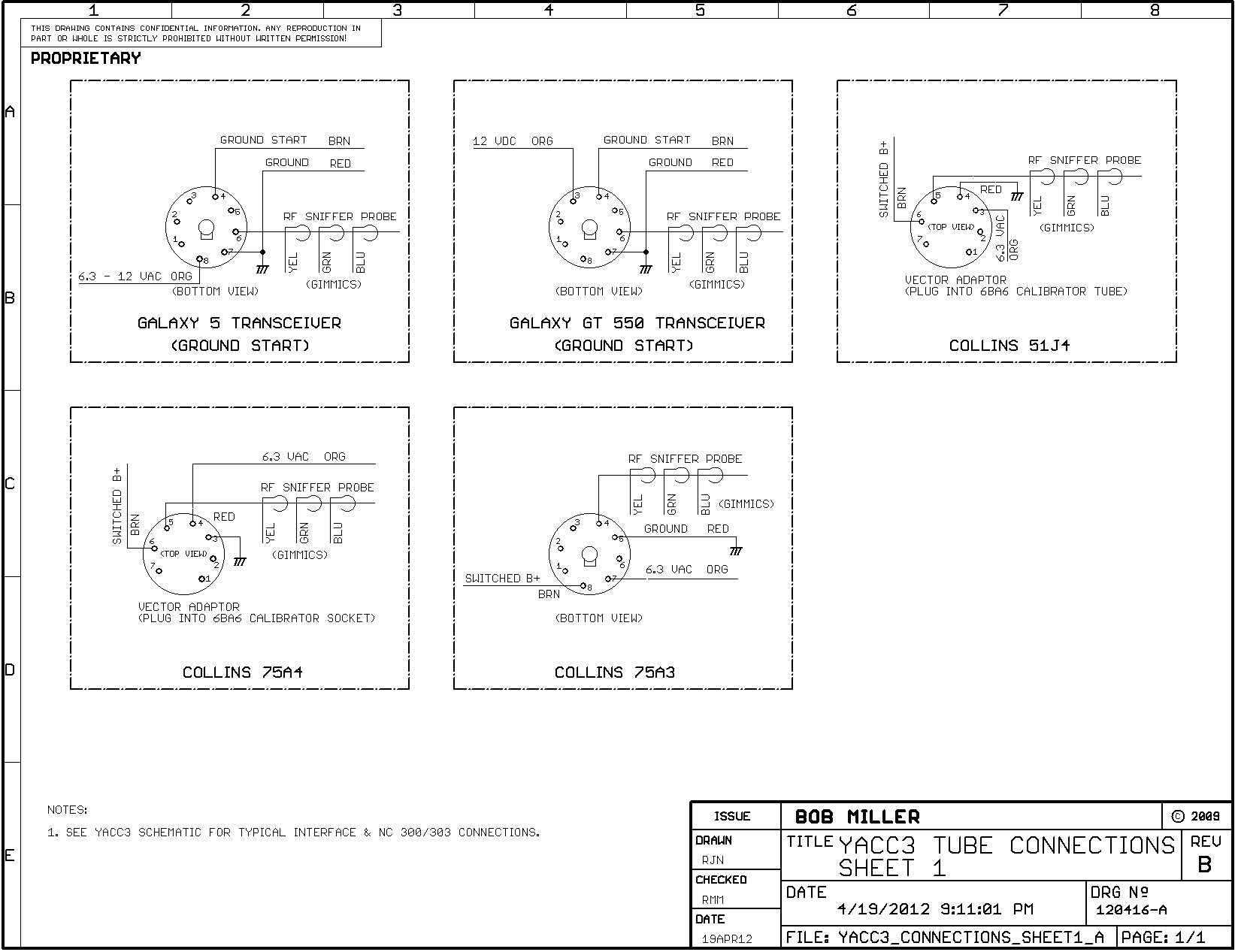
Miller 14 Pin Connector Wiring Diagrams are an essential tool for anyone working with electrical systems in welding equipment. These diagrams provide a visual representation of the wiring connections for the 14-pin connector used in Miller welding machines. By understanding how to read and interpret these diagrams, you can troubleshoot electrical problems, make necessary repairs, and ensure that your welding equipment operates safely and efficiently.
Why Miller 14 Pin Connector Wiring Diagrams are Essential
Miller 14 Pin Connector Wiring Diagrams are essential for several reasons:
- They provide a clear visual representation of the wiring connections for the 14-pin connector used in Miller welding machines.
- They help you identify the different components and connections within the wiring system.
- They allow you to troubleshoot electrical problems quickly and accurately.
- They serve as a reference guide for making repairs and modifications to the wiring system.
Reading and Interpreting Miller 14 Pin Connector Wiring Diagrams
When reading and interpreting Miller 14 Pin Connector Wiring Diagrams, it’s important to follow these steps:
- Identify the different components and connections within the diagram.
- Understand the symbols and color codes used in the diagram.
- Follow the wiring paths and connections to ensure proper installation and operation.
- Refer to the legend or key provided with the diagram for additional information.
Using Miller 14 Pin Connector Wiring Diagrams for Troubleshooting
Miller 14 Pin Connector Wiring Diagrams can be a valuable tool for troubleshooting electrical problems in welding equipment. Here’s how you can use them effectively:
- Identify the specific components or connections that may be causing the issue.
- Trace the wiring paths to locate any potential faults or damage.
- Use a multimeter to test the continuity and voltage at various points in the wiring system.
- Refer to the wiring diagram to ensure that the connections are correct and secure.
When working with electrical systems and using wiring diagrams, it’s important to prioritize safety. Here are some safety tips and best practices to keep in mind:
- Always turn off the power supply before working on any electrical equipment.
- Wear appropriate protective gear, such as gloves and safety glasses, to prevent accidents or injuries.
- Double-check your connections and wiring before powering up the equipment to avoid short circuits or electrical shocks.
- If you’re unsure about any aspect of the wiring system, consult a professional electrician or technician for assistance.
Miller 14 Pin Connector Wiring Diagram
Miller 14 Pin Connector Wiring Diagram – Wiring Diagram
Miller 14 Pin Connector Wiring Diagram – Free Wiring Diagram

miller 14 pin connector wiring diagram – TansyMaryam

Miller 14 Pin Connector Wiring Diagram Database

11+ miller 14 pin connector wiring diagram – FajarHendrix
miller 14 pin connector wiring diagram – DerecAniruddha
