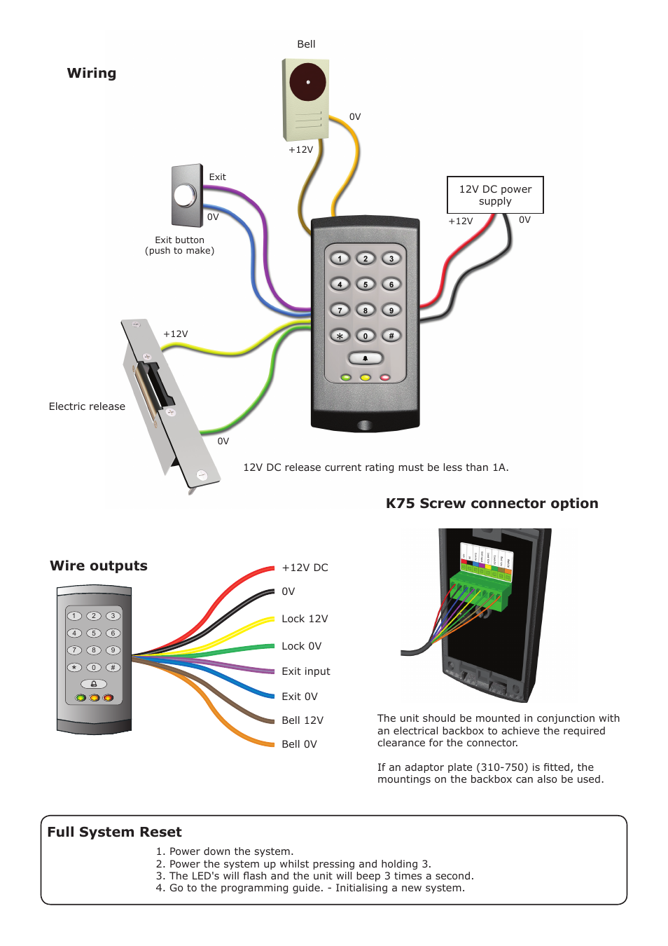
Maglock Wiring Diagrams are essential tools for understanding the electrical connections and components of magnetic locks. These diagrams provide a visual representation of how the different wires and components are connected in a maglock system, helping technicians troubleshoot issues and make necessary repairs. By following a maglock wiring diagram, you can ensure that the lock is properly installed and functioning correctly.
Why Maglock Wiring Diagrams are Essential
- Help technicians understand the electrical connections of maglocks
- Aid in troubleshooting electrical issues
- Ensure proper installation of maglock systems
- Provide a visual guide for wiring configurations
How to Read and Interpret Maglock Wiring Diagrams
When looking at a maglock wiring diagram, it’s important to understand the symbols and labels used in the diagram. Each wire and component will be represented by a specific symbol, and the connections between them will be indicated by lines. By following the lines and symbols, you can trace the flow of electricity through the system and identify any potential issues.
Using Maglock Wiring Diagrams for Troubleshooting
- Identify the location of components and wires in the system
- Check for loose connections or damaged wires
- Follow the flow of electricity to pinpoint the source of the issue
- Refer to the diagram to make necessary repairs or replacements
Importance of Safety
When working with electrical systems and using wiring diagrams, it is crucial to prioritize safety. Here are some safety tips to keep in mind:
- Always turn off the power before working on any electrical components
- Use insulated tools to prevent electric shock
- Avoid working in wet or damp conditions
- Double-check your connections before turning the power back on
Maglock Wiring Diagram
Wiring Diagram To Maglock Iei Keypad – Iei 212 Keypad Wiring Diagram

Maglock Wiring Diagram – Yarnens
Access Control Magnetic Door Lock Wiring Diagram

Wiring Diagram For Maglock

The Ultimate Guide to Dynalock Maglock Wiring Diagram: Step-by-Step

Magnetic Lock Wiring Diagram – Wiring Diagram
