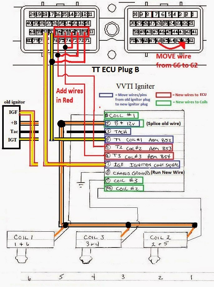
When it comes to understanding the electrical system of your vehicle, having a clear understanding of the Maf Sensor Wiring Diagram is crucial. This diagram provides a visual representation of the wiring connections for the Mass Air Flow (MAF) sensor in your vehicle, allowing you to troubleshoot and diagnose any electrical issues effectively.
Why Maf Sensor Wiring Diagrams are Essential
The Maf Sensor Wiring Diagram is essential for several reasons:
- It helps you understand the electrical connections of the MAF sensor in your vehicle.
- It allows you to identify any faulty wiring or connections that may be causing issues with the MAF sensor.
- It provides a roadmap for troubleshooting and diagnosing electrical problems related to the MAF sensor.
How to Read and Interpret Maf Sensor Wiring Diagrams Effectively
Reading and interpreting Maf Sensor Wiring Diagrams may seem daunting at first, but with the right approach, it can be a straightforward process:
- Start by familiarizing yourself with the symbols and color codes used in the diagram.
- Identify the components and connections represented in the diagram.
- Follow the wiring paths to understand how the electrical system is structured.
Using Maf Sensor Wiring Diagrams for Troubleshooting
Maf Sensor Wiring Diagrams are invaluable tools for troubleshooting electrical problems in your vehicle:
- By following the wiring diagram, you can pinpoint the source of any electrical issues affecting the MAF sensor.
- You can test the continuity of the wiring connections to identify any breaks or shorts.
- Using the diagram, you can make informed decisions on repairs or replacements needed to rectify the problem.
Importance of Safety When Working with Electrical Systems
When working with electrical systems and using wiring diagrams, safety should always be a top priority. Here are some safety tips and best practices to keep in mind:
- Always disconnect the battery before working on any electrical components to prevent the risk of electrical shock.
- Use insulated tools to avoid short circuits and electrical hazards.
- Double-check your connections and wiring before re-energizing the system to prevent damage to components or fires.
Maf Sensor Wiring Diagram
Maf Sensor Wiring Diagram Schematic

Toyota Maf Sensor Wiring Diagram – Eco Inc

How to Read and Understand a MAF Sensor Wiring Diagram

How to Read and Understand a MAF Sensor Wiring Diagram

Mass Air Flow Sensor Wiring Diagram – exatin.info

Part 4 -How To Test The MAF Sensor (2002-2003 3.5L Maxima)
