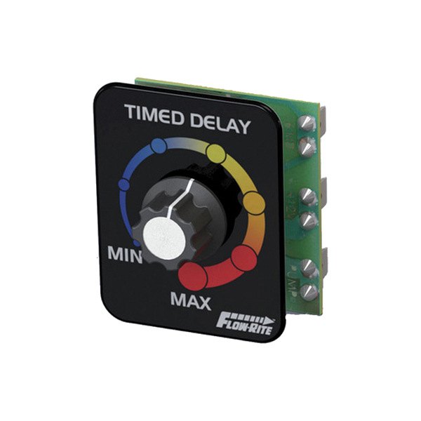
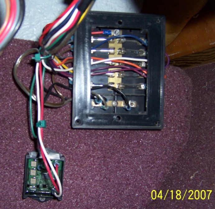
When it comes to Livewell Timer Wiring Diagram, it is important to understand the intricate details of how the wiring system works in order to effectively troubleshoot any electrical issues that may arise. Livewell Timer Wiring Diagrams provide a visual representation of the electrical connections within a livewell timer system, allowing mechanics to easily identify and fix any potential problems.
Importance of Livewell Timer Wiring Diagrams
Livewell Timer Wiring Diagrams are essential for several reasons:
- They provide a clear visual guide of the electrical connections within the livewell timer system
- They help mechanics understand how the system is wired and how each component functions
- They assist in troubleshooting electrical issues quickly and efficiently
Reading and Interpreting Livewell Timer Wiring Diagrams
When reading Livewell Timer Wiring Diagrams, it is important to pay attention to the following key components:
- Wire colors and labels to identify connections
- Symbols representing different electrical components
- Direction of current flow indicated by arrows
Using Livewell Timer Wiring Diagrams for Troubleshooting
Livewell Timer Wiring Diagrams can be incredibly useful when troubleshooting electrical problems. By following the diagram and tracing the electrical connections, mechanics can identify faulty components, loose connections, or other issues that may be causing problems within the system.
Safety Tips for Working with Livewell Timer Wiring Diagrams
Working with electrical systems can be dangerous, so it is essential to follow these safety tips:
- Always turn off power to the system before working on it
- Use insulated tools to prevent electric shock
- Double-check all connections before turning the power back on
- If unsure, seek the help of a professional electrician or mechanic
Livewell Timer Wiring Diagram
Boat Livewell Timer Installation
Timer Pod Kit – Contura V | Livewell Timer Kit – New Wire Marine

livewell timer module wiring diagram

Livewell Timer Wiring Diagram

Variable Livewell Timer – New Wire Marine

Boat Livewell Timer Installation
