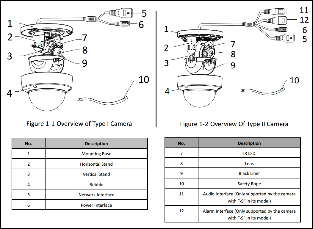
Ip Camera Pinout Wiring Diagrams are essential tools for anyone working with electrical systems, providing a visual representation of the connections between various components. These diagrams help users understand the layout of the wiring and how different parts of the system are interconnected.
Why Ip Camera Pinout Wiring Diagrams are essential
- Help in identifying the correct wires and connections
- Aid in troubleshooting electrical issues
- Ensure proper installation and maintenance of the system
- Provide a visual guide for understanding the wiring layout
Reading and interpreting Ip Camera Pinout Wiring Diagrams
When looking at an Ip Camera Pinout Wiring Diagram, it’s important to pay attention to the symbols and labels used. Each component will be represented by a specific symbol, and lines connecting them indicate the flow of electricity. Understanding these symbols and their meanings is crucial for interpreting the diagram accurately.
Using Ip Camera Pinout Wiring Diagrams for troubleshooting
- Identify the source of the electrical issue by tracing the connections in the diagram
- Check for loose connections or damaged wires based on the diagram
- Compare the actual wiring with the diagram to find discrepancies
- Follow the wiring layout to locate potential problem areas
Importance of safety
When working with electrical systems and using wiring diagrams, safety should always be a top priority. Some important safety tips include:
- Turn off power before working on any electrical components
- Use insulated tools to prevent electrical shock
- Avoid touching bare wires or components with wet hands
- Follow proper wiring practices to prevent short circuits and fires
Ip Camera Pinout Wiring Diagram
Hikvision IP Camera RJ45 Pin-Out (wiring) — SecurityCamCenter.com

How to Install PoE IP CCTV Cameras with NVR Security System

Ip Camera Pinout Wiring Diagram – Easy Wiring

Hikvision Ip Camera Wiring Diagram – Uploadled

Poe ip camera wiring diagram – fivirt

Ip camera pinout wiring diagram – musebinger
