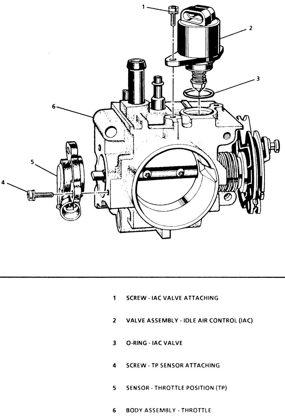
Idle Air Control Valve Wiring Diagram
An Idle Air Control Valve Wiring Diagram is a schematic representation of the electrical connections for the idle air control valve in a vehicle. This diagram shows the various wires, connectors, and components involved in the electrical system of the idle air control valve.
Importance of Idle Air Control Valve Wiring Diagram
Idle Air Control Valve Wiring Diagrams are essential for the following reasons:
- Helps in diagnosing and troubleshooting electrical issues related to the idle air control valve
- Provides a visual representation of the wiring connections, making it easier to understand the system
- Aids in identifying the correct wires and connectors for proper installation and repair
Reading and Interpreting Idle Air Control Valve Wiring Diagram
When reading an Idle Air Control Valve Wiring Diagram, it’s important to:
- Understand the symbols and color codes used in the diagram
- Follow the wiring paths and connections to identify any potential issues
- Refer to the vehicle’s service manual for specific details and instructions
Using Wiring Diagrams for Troubleshooting
Idle Air Control Valve Wiring Diagrams are useful for troubleshooting electrical problems by:
- Identifying faulty connections or damaged wires
- Checking for voltage and continuity at different points in the circuit
- Testing components for proper functionality
By following the wiring diagram, mechanics can efficiently diagnose and repair electrical issues related to the idle air control valve.
Safety Tips and Best Practices
When working with Idle Air Control Valve Wiring Diagrams or any electrical system, it’s important to follow these safety tips:
- Always disconnect the battery before working on the electrical system
- Use insulated tools to prevent electrical shocks
- Avoid working on electrical components in wet or damp conditions
- Double-check all connections and wiring before reassembling the system
Following these safety precautions will help prevent accidents and ensure a successful repair process when working with Idle Air Control Valve Wiring Diagrams.
Idle Air Control Valve Wiring Diagram
Wiring and Configuring Outputs on Different Types of Idle Actuators

Idle Air Control Valve Wiring Diagram

Idle Air Control valve Wiring|IAC valve|Complete Wiring|And Complete

Idle Air Control Valve Wiring Diagram: A Comprehensive Guide – Moo Wiring

Idle Air Control Valve Wire Diagram Needed?

| Repair Guides | Electronic Engine Controls | Idle Air Control (iac
