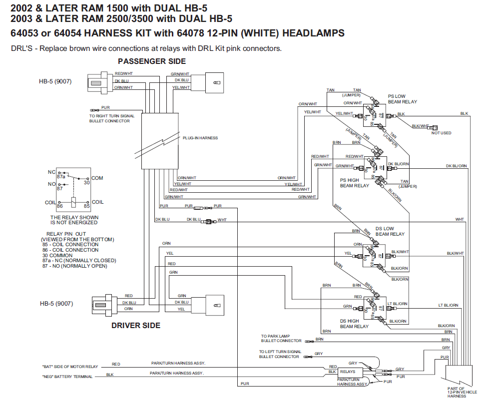
When it comes to working on Hiniker plows, having a comprehensive understanding of the wiring diagram is crucial. The Hiniker Plow Wiring Diagram serves as a roadmap for the electrical system of the plow, assisting in proper installation, maintenance, and troubleshooting. In this article, we will explore the importance of Hiniker Plow Wiring Diagram and how to effectively utilize them.
Why Hiniker Plow Wiring Diagram are essential
The Hiniker Plow Wiring Diagram is essential for the following reasons:
- Ensures proper installation of the plow
- Guides maintenance and repairs
- Facilitates troubleshooting electrical issues
- Helps in understanding the electrical connections and components
Reading and interpreting Hiniker Plow Wiring Diagram
Reading and interpreting Hiniker Plow Wiring Diagram effectively involves understanding the symbols, colors, and connections. Here are some tips:
- Refer to the legend or key provided in the diagram for symbol meanings
- Identify the color-coding of wires for easy tracing
- Follow the directional flow of the wiring diagram
- Pay attention to the connections and terminals
Using Hiniker Plow Wiring Diagram for troubleshooting
Hiniker Plow Wiring Diagram can be a valuable tool for troubleshooting electrical problems. Here’s how to utilize them:
- Identify the specific circuit or component causing the issue
- Follow the wiring diagram to trace the connections and potential faults
- Check for continuity, voltage, and resistance at various points as indicated in the diagram
- Compare the actual wiring with the diagram to detect any discrepancies
Importance of safety
Working with electrical systems can be hazardous, so it’s crucial to prioritize safety. Here are some safety tips when using Hiniker Plow Wiring Diagram:
- Always disconnect the power source before working on the electrical system
- Use insulated tools to prevent electrical shocks
- Avoid working in wet or damp conditions to prevent electrical hazards
- Double-check all connections and wiring before restoring power
Hiniker Plow Wiring Diagram
Hiniker Snow Plow Wiring Diagram

Hiniker Snow Plow Wiring Diagram Pdf

How to Easily Install and Connect a Hiniker Plow Wiring Diagram

How to Easily Install and Connect a Hiniker Plow Wiring Diagram

Bestio: Hiniker Snow Plow Wiring Diagram
