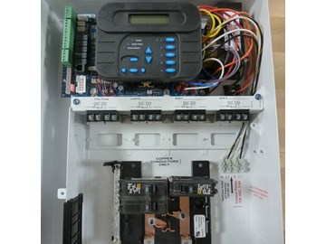
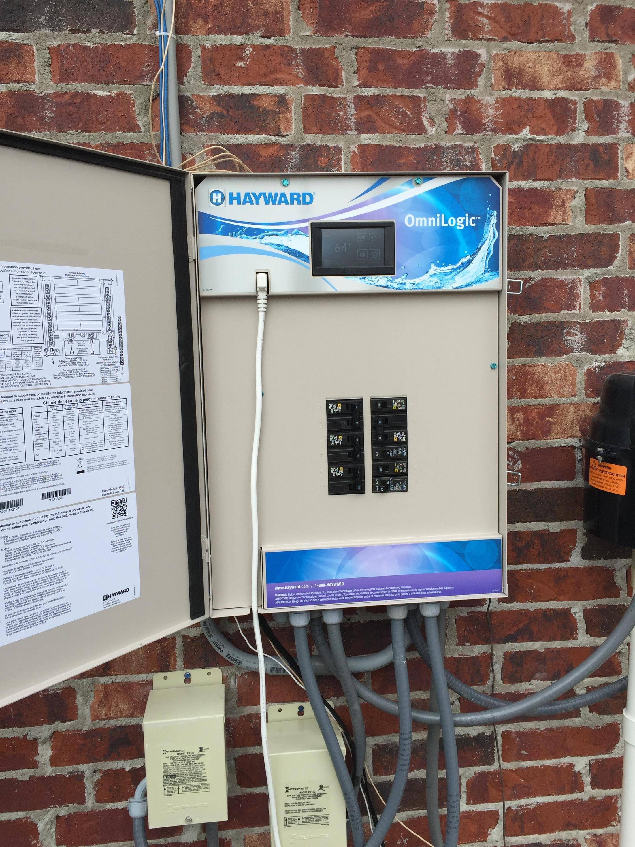
Hayward Pro Logic Wiring Diagrams are essential tools for anyone working with Hayward Pro Logic systems. These diagrams provide a visual representation of the electrical connections within the system, helping users understand how different components are wired together.
Why are Hayward Pro Logic Wiring Diagrams Essential?
- Ensure proper installation of the system
- Aid in troubleshooting electrical issues
- Help in understanding the system’s functionality
Reading and Interpreting Hayward Pro Logic Wiring Diagrams
When looking at a Hayward Pro Logic Wiring Diagram, it’s important to understand the symbols and labels used in the diagram. Each component is represented by a specific symbol, and the lines connecting these components show how they are connected electrically.
- Study the legend or key to understand the symbols used
- Follow the lines to trace the electrical connections
- Pay attention to labels and numbers for each component
Using Hayward Pro Logic Wiring Diagrams for Troubleshooting
Hayward Pro Logic Wiring Diagrams are valuable tools when troubleshooting electrical problems within the system. By following the wiring diagram, you can identify potential issues such as loose connections, faulty components, or incorrect wiring.
- Compare the actual wiring to the diagram to spot discrepancies
- Use a multimeter to test continuity and voltage at different points
- Refer to the troubleshooting section of the manual for common issues
Importance of Safety
When working with electrical systems and using wiring diagrams, safety should always be a top priority. Follow these safety tips and best practices to prevent accidents and ensure a successful installation or repair:
- Always turn off power before working on the system
- Use insulated tools to prevent electric shock
- Avoid working in wet or damp conditions
- Double-check all connections before restoring power
Hayward Pro Logic Wiring Diagram
How to Wire 115V Equipment to the Hayward Pro Logic – INYOPools.com

How To Wire A 2-Speed 230V Motor to a Hayward Pro Logic System

How to Wire 230V Equipment to the Hayward Pro Logic – INYOPools.com

hayward pro logic wiring diagram – AnitaAliah

Hayward Pro Logic Wiring Diagram

Hayward Pro Logic Wiring Diagram
