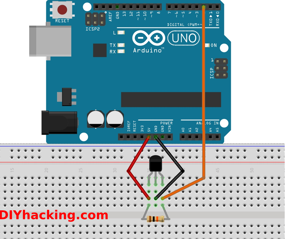
Understanding the Hall Effect Sensor Wiring Diagram is crucial for any mechanic or technician working with electrical systems. This diagram provides a visual representation of how the sensor is wired into a circuit, helping to troubleshoot issues and ensure proper installation.
Why Hall Effect Sensor Wiring Diagrams are Essential
Hall Effect Sensor Wiring Diagrams are essential for the following reasons:
- Helps in understanding the wiring connections of the sensor
- Aids in troubleshooting electrical issues
- Ensures proper installation of the sensor
Reading and Interpreting Hall Effect Sensor Wiring Diagrams
Reading and interpreting Hall Effect Sensor Wiring Diagrams can be daunting, but with the right guidance, it becomes easier. Here are some tips to help you:
- Identify the components: Understand the symbols used in the diagram
- Follow the wiring: Trace the wires from the sensor to the control unit
- Check for connections: Ensure all connections are correct and secure
Using Hall Effect Sensor Wiring Diagrams for Troubleshooting
Hall Effect Sensor Wiring Diagrams are invaluable for troubleshooting electrical problems. Here’s how you can use them effectively:
- Identify the sensor location: Locate the sensor on the diagram to pinpoint any issues
- Check for continuity: Use a multimeter to test for continuity along the wiring paths
- Look for shorts or open circuits: Identify any shorts or open circuits that may be causing the problem
Importance of Safety
When working with electrical systems and using wiring diagrams, safety should be a top priority. Here are some safety tips and best practices:
- Always disconnect power before working on any electrical components
- Use insulated tools to prevent electrical shocks
- Double-check all connections before powering up the system
Hall Effect Sensor Wiring Diagram
A Simple Guide to Using a Hall Effect Sensor With Arduino

Wiring the 314X Hall Effect Sensor Module | 14core.com

Using a Hall Effect Sensor with Arduino – Electronics-Lab

Interfacing A3144 Hall Effect Sensor with Arduino UNO

Hall effect sensor wiring diagram and test video

Interfacing Hall Effect sensor with Arduino – Hackster.io
