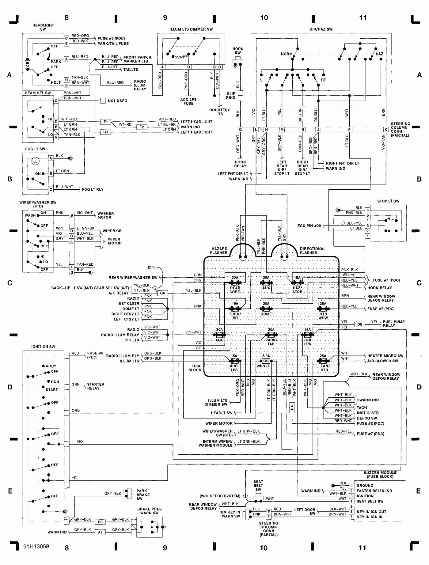
Grote Turn Signal Wiring Diagram
When it comes to understanding the electrical system of your vehicle, having a Grote Turn Signal Wiring Diagram can be incredibly helpful. These diagrams provide a visual representation of the wiring layout for your turn signals, making it easier to troubleshoot any issues that may arise.
Why Grote Turn Signal Wiring Diagrams are Essential
- Helps in understanding the wiring configuration of the turn signal system
- Aids in diagnosing and fixing electrical problems
- Ensures proper installation and connection of components
Reading and Interpreting Grote Turn Signal Wiring Diagrams
Reading and interpreting a Grote Turn Signal Wiring Diagram may seem daunting at first, but with a little guidance, it can become much easier. Here are some tips:
- Understand the symbols and colors used in the diagram
- Follow the flow of the wiring from component to component
- Pay attention to the connections and grounds
Using Grote Turn Signal Wiring Diagrams for Troubleshooting
When faced with electrical problems in your turn signal system, a Grote Turn Signal Wiring Diagram can be your best friend. Here’s how you can use it for troubleshooting:
- Identify the specific area where the issue may be occurring
- Trace the wiring to check for any breaks or loose connections
- Refer to the diagram to understand the circuit and locate the problem
Remember, safety should always be a top priority when working with electrical systems. Here are some safety tips to keep in mind:
- Always disconnect the battery before working on any electrical components
- Use insulated tools to prevent electrical shocks
- Avoid working on the wiring when the vehicle is running
- If you’re unsure about a certain procedure, consult a professional mechanic
Grote Turn Signal Wiring Diagram
Grote Turn Signal Switch Wiring Diagram | Wiringdiagram – Turn Signal

Grote Turn Signal Wiring Diagram – Wiring Diagram Pictures

The Ultimate Guide: Grote Turn Signal Switch Wiring Diagram Explained

Grote Turn Signal Switch Wiring Diagram 4807 – Great Installation Of

Grote 44890 | Wiring Diagram Image

Grote Turn Signal Switch Wiring Diagram 4807 – Great Installation Of
