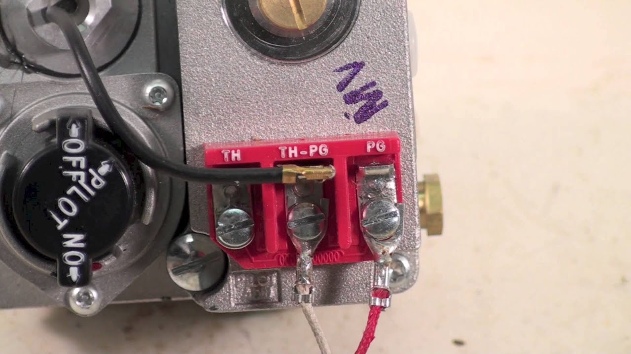
Gas valve wiring diagrams are essential tools for mechanics and technicians working on gas-powered appliances such as furnaces, boilers, and water heaters. These diagrams provide a visual representation of the electrical connections within the gas valve system, helping to ensure proper installation, maintenance, and troubleshooting.
Importance of Gas Valve Wiring Diagrams
Gas valve wiring diagrams are essential for the following reasons:
- Ensure proper installation of gas valve systems
- Facilitate troubleshooting of electrical issues
- Help in identifying faulty components
- Ensure safety by following correct wiring connections
Reading and Interpreting Gas Valve Wiring Diagrams
When reading a gas valve wiring diagram, it is important to pay attention to the following:
- Identify the different components and their corresponding symbols
- Follow the wiring paths to understand the electrical connections
- Check for color codes to differentiate between wires
Using Gas Valve Wiring Diagrams for Troubleshooting
Gas valve wiring diagrams can be used effectively for troubleshooting electrical problems by:
- Identifying the source of the issue based on the wiring connections
- Testing the continuity of wires and components using a multimeter
- Comparing the actual wiring connections with the diagram to spot discrepancies
Safety Tips for Working with Gas Valve Wiring Diagrams
When working with gas valve wiring diagrams, it is crucial to prioritize safety. Here are some safety tips and best practices:
- Always turn off the power supply before working on electrical systems
- Use insulated tools to prevent electrical shocks
- Avoid working on live circuits to prevent accidents
- Double-check the wiring connections before powering up the system
Gas Valve Wiring Diagram
️Robertshaw Gas Valve Wiring Diagram Free Download| Gmbar.co

Wiring Diagram For Furnace Gas Valve – Wiring Diagram

Rinnai R85 Gas Valve Wiring Diagram

Honeywell Smart Gas Valve Wiring Diagram – Wiring Diagram

Millivolt Gas Valve Wiring Diagram

Honeywell Vr8200 Gas Valve Wiring Diagram
