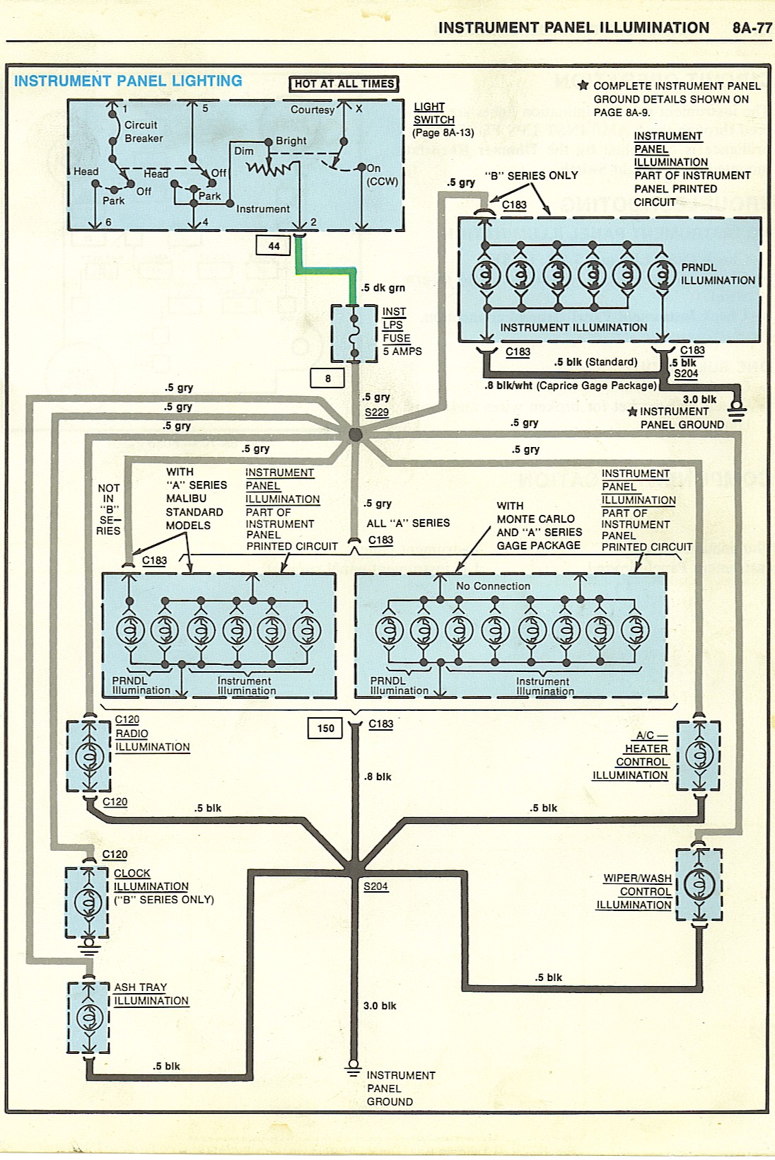
When working on your car’s electrical system, having a clear understanding of the G body Gauge Cluster Wiring Diagram is crucial. This diagram shows the layout of the wires and connections in your vehicle’s gauge cluster, helping you navigate the complex network of electrical components.
Why are G body Gauge Cluster Wiring Diagrams essential?
- Provide a visual representation of the electrical connections in your gauge cluster
- Help troubleshoot electrical issues efficiently
- Ensure proper installation and maintenance of the gauge cluster
How to read and interpret G body Gauge Cluster Wiring Diagrams effectively
Reading and interpreting a G body Gauge Cluster Wiring Diagram can seem daunting at first, but with the right approach, it becomes a valuable tool for any mechanic. Here are some tips:
- Start by familiarizing yourself with the diagram’s key symbols and colors
- Follow the lines to trace the path of the wires and connections
- Pay attention to labels and legends for clarity
Using G body Gauge Cluster Wiring Diagrams for troubleshooting electrical problems
When facing electrical issues in your vehicle, the G body Gauge Cluster Wiring Diagram can be your best friend. Here’s how you can use it effectively:
- Identify the specific circuit or component causing the problem
- Trace the wiring to locate any faulty connections or damaged wires
- Refer to the diagram to understand how the different components are interconnected
Remember, safety should always be a top priority when working with electrical systems and wiring diagrams. Here are some key safety tips:
- Always disconnect the battery before working on any electrical components
- Use insulated tools to prevent electrical shocks
- Double-check your connections before powering up the system
G body Gauge Cluster Wiring Diagram
G-body Gauge Cluster Wiring Diagram

5+ g-body gauge cluster wiring diagram – ArminderRuno

G-Body Gauge Cluster Wiring Diagram – Wiring Diagram

5+ g-body gauge cluster wiring diagram – DonaldaMaythu

G Body Engine Wiring Diagram and Wiring Diagrams – 10+ G Body Engine

5+ g-body gauge cluster wiring diagram – OpheTammay
