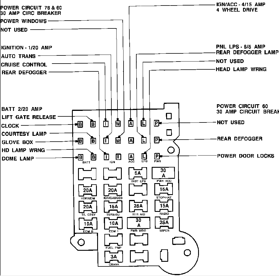
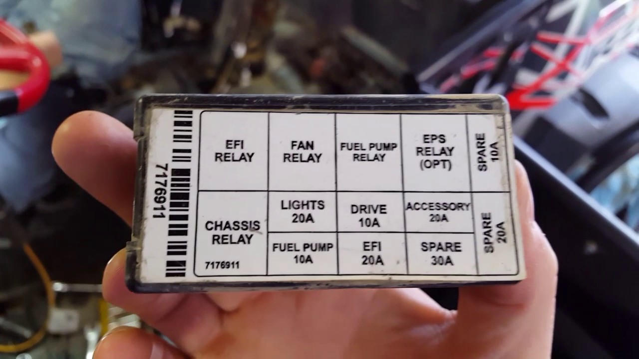
Understanding how to read and interpret a fuse box wiring diagram is essential for any mechanic or DIY enthusiast working on electrical systems in vehicles. A fuse box wiring diagram provides a visual representation of the electrical connections and components within the fuse box, helping to identify which fuses control specific circuits and ensuring proper troubleshooting and maintenance.
Why Fuse Box Wiring Diagrams are Essential
- Help in identifying which fuses control specific circuits
- Aid in troubleshooting electrical problems
- Ensure proper maintenance of electrical systems
How to Read and Interpret Fuse Box Wiring Diagrams Effectively
When looking at a fuse box wiring diagram, it’s important to understand the symbols and markings used to represent different components and connections. Here are some key tips for reading and interpreting fuse box wiring diagrams:
- Identify the key components such as fuses, relays, connectors, and wires
- Follow the wiring paths to understand the flow of electricity through the system
- Pay attention to color coding and labeling for easier interpretation
Using Fuse Box Wiring Diagrams for Troubleshooting Electrical Problems
Fuse box wiring diagrams are invaluable tools when troubleshooting electrical issues in vehicles. By referencing the diagram, you can quickly pinpoint the location of specific components and connections, making it easier to diagnose and fix problems such as blown fuses, short circuits, or faulty wiring.
Safety Tips for Working with Fuse Box Wiring Diagrams
- Always disconnect the vehicle’s battery before working on electrical systems
- Use insulated tools to prevent electric shock
- Avoid working on electrical systems in wet or damp conditions
- Double-check connections and wiring before restoring power to the system
By following these guidelines and utilizing fuse box wiring diagrams effectively, you can ensure safe and successful maintenance and troubleshooting of electrical systems in vehicles.
Fuse Box Wiring Diagram
Consumer Unit Fuse Box Wiring Diagram Stock Image – Image of install

New Fuse Box – Wiring Diagram

1998 Chevy Blazer Fuse Box Diagram

Fuse Box Diagram House – limitorque wiring diagram

Rzr 1000 Xp Term Fuse Box Wiring Diagram

1957 Chevy Fuse Box Wiring Diagram
