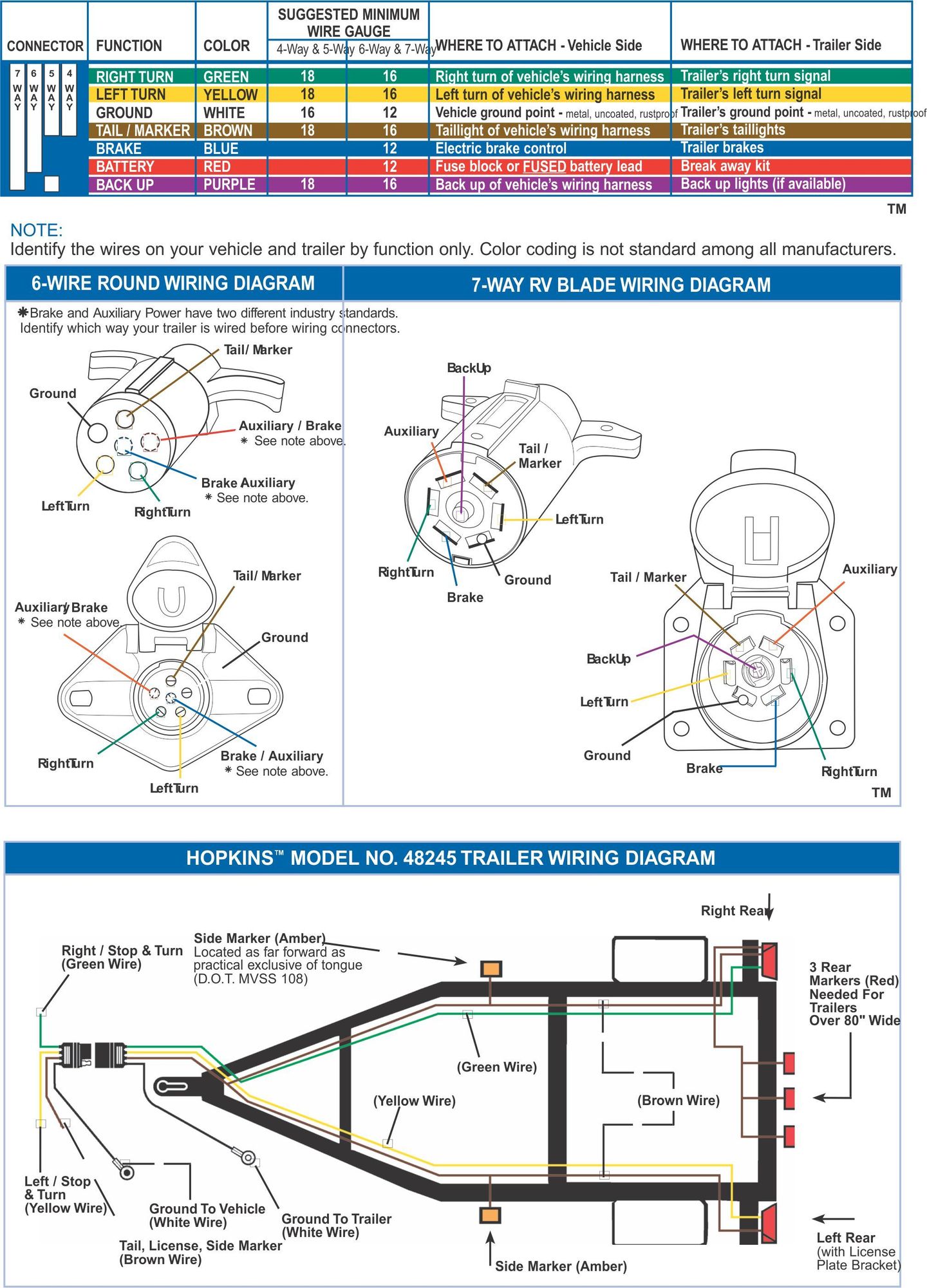
When it comes to ensuring the safety and efficiency of your Ford vehicle’s braking system, understanding the Ford Brake Controller Wiring Diagram is crucial. This diagram provides a detailed outline of how the brake controller is wired into the vehicle’s electrical system, allowing for proper installation and operation.
Why are Ford Brake Controller Wiring Diagrams Essential?
Ford Brake Controller Wiring Diagrams are essential for several reasons:
- They help ensure the correct installation of the brake controller.
- They provide a clear understanding of how the brake controller interacts with the vehicle’s electrical system.
- They aid in troubleshooting electrical issues related to the brake controller.
How to Read and Interpret Ford Brake Controller Wiring Diagrams Effectively
Reading and interpreting Ford Brake Controller Wiring Diagrams can be daunting, but with the right approach, it can be simplified:
- Start by familiarizing yourself with the key symbols and color codes used in the diagram.
- Follow the flow of the wiring diagram from the power source to the brake controller and associated components.
- Pay close attention to the connections and wiring paths to ensure accuracy during installation.
Using Ford Brake Controller Wiring Diagrams for Troubleshooting Electrical Problems
Ford Brake Controller Wiring Diagrams are invaluable when it comes to troubleshooting electrical problems:
- Identify any loose or disconnected wires that may be causing issues with the brake controller.
- Check for continuity and proper voltage levels at key connection points to pinpoint the source of the problem.
- Refer to the wiring diagram to ensure all components are properly connected and functioning as intended.
Importance of Safety When Working with Electrical Systems
When working with electrical systems and using wiring diagrams, safety should always be the top priority:
- Disconnect the vehicle’s battery before starting any electrical work to prevent the risk of electrical shock.
- Use insulated tools and wear appropriate safety gear, such as gloves and safety glasses, to protect yourself from potential hazards.
- Double-check all connections and wiring before re-connecting the battery to avoid short circuits or other electrical issues.
Ford Brake Controller Wiring Diagram
86 F150 Tail Light Wiring Diagram

Atlas Controller Wiring Diagram

4 Way Truck Wiring Diagram

1996 Ford F150 Starter

Ac Wiring Diagram 2007 Chevy 2500

Wiring Diagrams For Trailers
