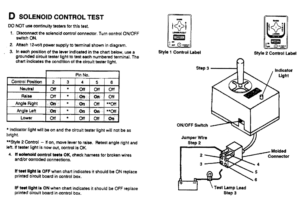
Fisher Snow Plow Controller Wiring Diagram is a crucial tool for understanding the electrical system of your snow plow controller. It provides a visual representation of the connections between various components and helps you troubleshoot any issues that may arise.
Why Fisher Snow Plow Controller Wiring Diagram are essential:
- Ensure proper installation of the controller
- Identify and fix any electrical issues
- Understand the wiring layout for maintenance and repairs
How to read and interpret Fisher Snow Plow Controller Wiring Diagram:
When looking at a wiring diagram, it is essential to understand the symbols and color codes used. Follow the lines connecting the components to trace the electrical connections. Refer to the legend or key provided to decipher the diagram accurately.
How to use Fisher Snow Plow Controller Wiring Diagram for troubleshooting:
- Identify the components involved in the problem
- Check for continuity and proper voltage levels
- Trace the wiring to locate any loose connections or damaged wires
Importance of safety when working with electrical systems:
Working with electrical systems can be dangerous if proper precautions are not taken. Here are some safety tips to keep in mind:
- Always disconnect the power source before working on the wiring
- Use insulated tools to prevent electrical shocks
- Avoid working in wet or damp conditions
- Double-check your work before restoring power to the system
Fisher Snow Plow Controller Wiring Diagram
Fisher Snow Plow Wiring Diagram – Wiring Diagram

Fisher Snow Plow Controller Wiring Diagram – Wiring Diagram
Fisher Plow Control Wiring Diagram

Fisher Plow Wiring Diagram Troubleshooting – wiring diagram creator

How to Properly Wire a Fisher Snow Plow Controller: A Step-by-Step

How to Properly Wire a Fisher Snow Plow Controller: A Step-by-Step
