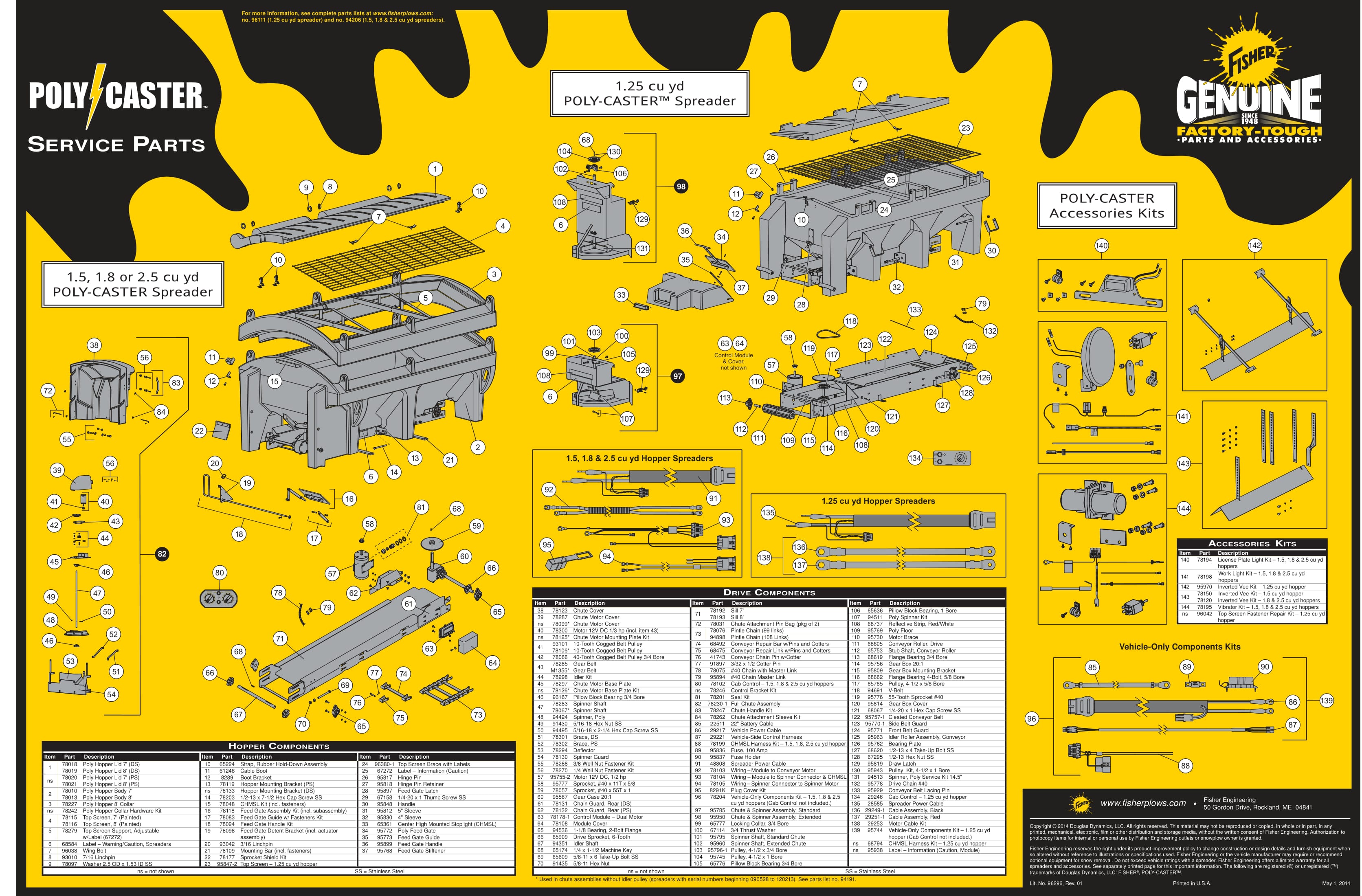
When it comes to maintaining and troubleshooting electrical systems in vehicles, having access to a Fisher Poly Caster Wiring Diagram is essential. This diagram provides a visual representation of the electrical connections and components within the Fisher Poly Caster salt spreader, helping mechanics and technicians understand how the system is wired.
Why Fisher Poly Caster Wiring Diagrams are Essential
Understanding the wiring diagram for a Fisher Poly Caster salt spreader is crucial for several reasons:
- Helps identify the location of electrical components
- Aids in diagnosing electrical issues
- Assists in proper installation and repair
Reading and Interpreting Fisher Poly Caster Wiring Diagrams
Reading a Fisher Poly Caster Wiring Diagram may seem daunting at first, but with the right approach, it can be a valuable tool:
- Identify the symbols and colors used in the diagram
- Follow the flow of the electrical connections
- Refer to the legend or key for clarification
Using Wiring Diagrams for Troubleshooting
When faced with electrical problems in a Fisher Poly Caster salt spreader, the wiring diagram can be a lifesaver:
- Locate the affected components and connections
- Check for continuity and voltage at specific points
- Compare the actual wiring to the diagram for discrepancies
Importance of Safety
Working with electrical systems can be dangerous, so it’s important to follow safety protocols:
- Always disconnect the power source before working on the system
- Use insulated tools to avoid electrical shock
- Avoid working on wet surfaces or in damp conditions
By following these safety tips and utilizing Fisher Poly Caster Wiring Diagrams effectively, mechanics can ensure a safe and successful repair or maintenance job on the salt spreader’s electrical system.
Fisher Poly Caster Wiring Diagram
The Ultimate Guide to Understanding Fisher Poly Caster Sander Wiring

POLY-CASTER™ Spreader | Poly Broadcast Spreader | FISHER®

Fisher Poly Caster Sander Wiring Diagram – Wiring Diagram

Fisher Poly-Caster Spreader Parts

The Ultimate Guide to Understanding Fisher Poly Caster Wiring Diagrams

FISHER POLY-CASTER INSTALLATION INSTRUCTIONS MANUAL Pdf Download
