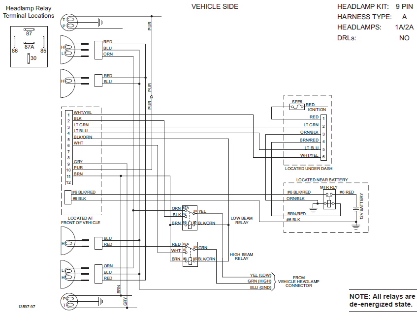
When it comes to installing or troubleshooting a Fisher plow light system, having a Fisher Plow Light Wiring Diagram is essential. This diagram provides a visual representation of the wiring connections and electrical components involved in the system, making it easier to understand and work with.
Why Fisher Plow Light Wiring Diagrams are essential
- Helps in understanding the wiring connections
- Ensures proper installation of the light system
- Aids in troubleshooting electrical issues
- Provides a reference guide for future maintenance or repairs
How to read and interpret Fisher Plow Light Wiring Diagram effectively
When looking at a Fisher Plow Light Wiring Diagram, it’s important to pay attention to the symbols, colors, and connections indicated. Here are some tips for reading and interpreting the diagram effectively:
- Identify the key components such as lights, relays, switches, and connectors
- Follow the wiring paths and connections to understand how the system is wired
- Take note of any color codes or symbols used to denote specific components or wiring functions
- Refer to the legend or key provided in the diagram for further clarification
Using Fisher Plow Light Wiring Diagrams for troubleshooting electrical problems
When faced with electrical issues in a Fisher plow light system, the wiring diagram can be a valuable tool for troubleshooting. Here’s how you can use the diagram effectively:
- Identify the specific circuit or component that is causing the issue
- Trace the wiring connections to check for any loose or damaged wires
- Use a multimeter to test the continuity and voltage of the electrical connections
- Refer to the wiring diagram to ensure that the connections are correct and in the right sequence
Remember, safety should always be a top priority when working with electrical systems and wiring diagrams. Here are some safety tips and best practices to keep in mind:
- Always disconnect the power source before working on any electrical components
- Use insulated tools and wear protective gear such as gloves and goggles
- Double-check your connections and wiring before applying power to the system
- If you are unsure or uncomfortable working with electrical systems, it’s best to seek professional help
Fisher Plow Light Wiring Diagram
Fisher Plow Headlight Wiring Diagram

The Ultimate Guide to Understanding Fisher Plow Lights Wiring Diagrams

how a fisher plow solenoid works – Wiring Digital and Schematic
66610 MVP Western / Fisher Unimount Truck side 12 pin light wiring

Fisher Plow Light Wiring Diagram – Database – Wiring Collection

Fisher Minute Mount 2 Headlight Wiring Diagram – Schema Wiring Diagram
