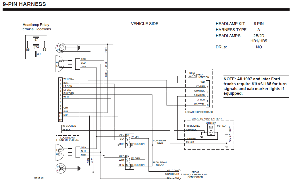
Are you looking for information on Fisher Plow Controller Wiring Diagram? Understanding the wiring diagram is crucial for proper installation and maintenance of your Fisher plow controller. Let’s delve into the details of Fisher Plow Controller Wiring Diagram and how it can help you with your plow system.
Why Fisher Plow Controller Wiring Diagrams are essential
Wiring diagrams for Fisher Plow Controllers are essential for several reasons:
- Ensure proper installation of the controller
- Help in troubleshooting electrical issues
- Provide guidance on wiring connections
Reading and interpreting Fisher Plow Controller Wiring Diagrams
When reading a Fisher Plow Controller Wiring Diagram, it’s important to pay attention to the following:
- Color coding of wires
- Connection points for different components
- Understanding the flow of electricity through the system
Using Fisher Plow Controller Wiring Diagrams for troubleshooting
Fisher Plow Controller Wiring Diagrams are invaluable when troubleshooting electrical problems. By following the diagram, you can:
- Identify faulty connections or components
- Trace the flow of electricity to pinpoint the issue
- Ensure all connections are secure and properly installed
Importance of safety when working with electrical systems
When working with electrical systems and using wiring diagrams, safety should always be a top priority. Here are some safety tips and best practices to keep in mind:
- Always turn off the power source before working on any electrical components
- Use proper tools and equipment to prevent electric shocks
- Avoid working in wet or damp conditions
- Double-check all connections before energizing the system
Fisher Plow Controller Wiring Diagram
Fisher Snow Plow Wiring Diagram – Wiring Diagram

Fisher Plow Controller Wiring Diagram For Your Needs

Fisher Plow 6 Pin Controller Wiring Diagram: Simplifying Installation

Fisher Plow Wiring Diagram – Wiring Diagram

Fisher Plow Controller Wiring Diagram – Easy Wiring
Fisher Plow Controller Wiring Diagram For Your Needs
