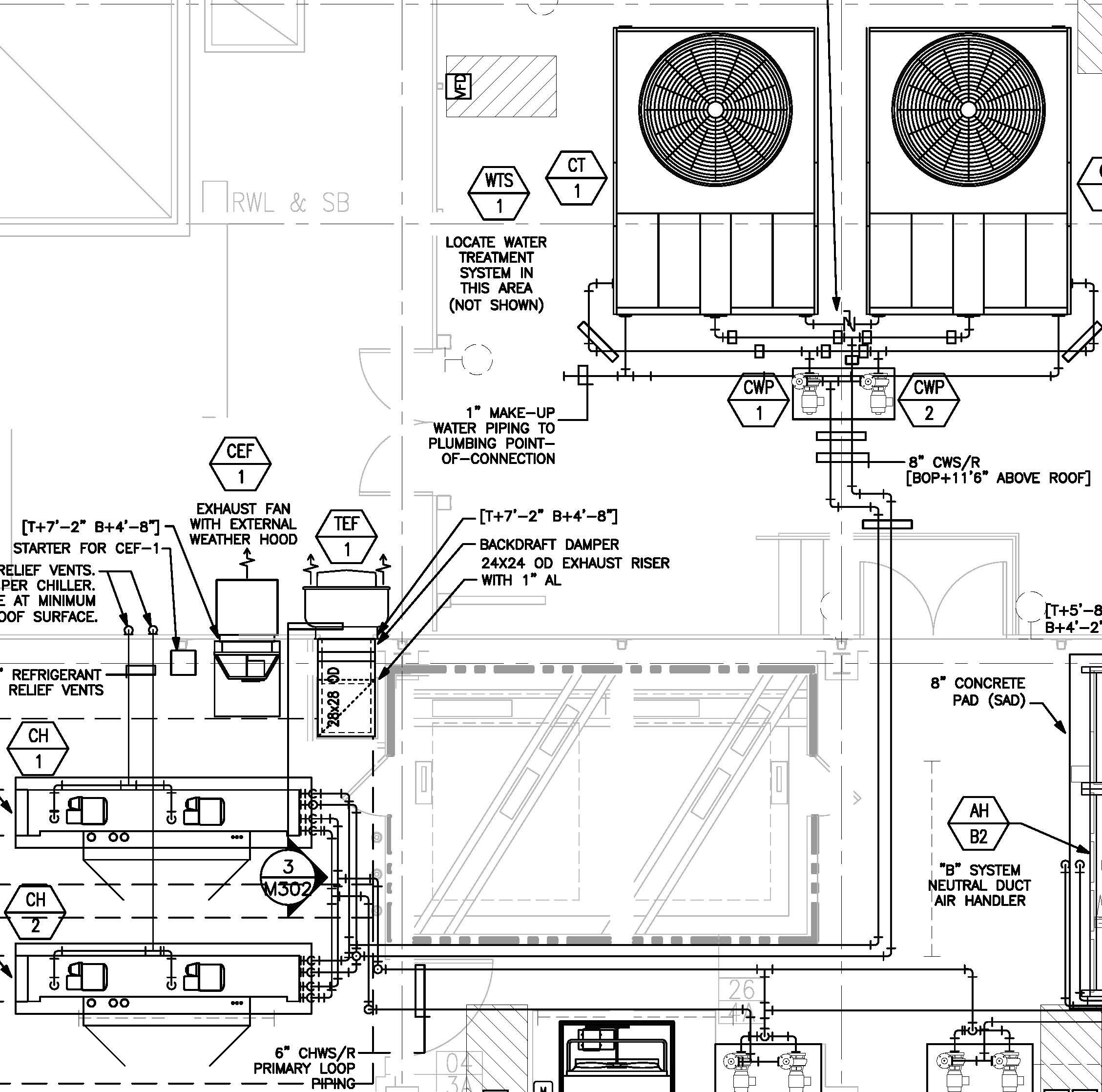
When it comes to understanding and troubleshooting the electrical systems of First Company air handlers, having access to a wiring diagram is essential. A First Company Air Handler Wiring Diagram provides a visual representation of the electrical connections within the unit, helping technicians to identify components, trace circuits, and diagnose issues effectively.
Why First Company Air Handler Wiring Diagrams are Essential
- Helps in understanding the electrical layout of the air handler
- Aids in troubleshooting electrical problems efficiently
- Provides a visual guide for installation and repairs
- Ensures proper maintenance of the unit
How to Read and Interpret First Company Air Handler Wiring Diagrams
When looking at a First Company Air Handler Wiring Diagram, it’s important to understand the symbols and color codes used. Each component in the diagram is represented by a specific symbol, with lines connecting them to show how they are connected electrically. Color codes are used to differentiate between different wires and their functions.
Using First Company Air Handler Wiring Diagrams for Troubleshooting
- Identify the components and their connections
- Trace circuits to locate potential issues
- Check for continuity and proper voltage levels
- Refer to the diagram while conducting tests and inspections
It’s crucial to follow safety precautions when working with electrical systems and using wiring diagrams. Here are some important safety tips to keep in mind:
- Always turn off the power supply before working on the unit
- Use insulated tools to avoid electric shocks
- Double-check connections before powering the unit back on
- Wear appropriate protective gear, such as gloves and goggles
First Company Air Handler Wiring Diagram
First Company Air Handler Wiring Diagram – Cadician's Blog

The Ultimate Guide to Understanding Air Handler Wiring Diagrams for

The Ultimate Guide to Understanding Air Handler Wiring Diagrams for

⭐ First Company Air Handler Wiring ⭐ – Diy imagination

First Company Air Handler Wiring Diagram – General Wiring Diagram

[DIAGRAM] First Company Air Handler Wiring Diagram – MYDIAGRAM.ONLINE
![First Company Air Handler Wiring Diagram [DIAGRAM] First Company Air Handler Wiring Diagram - MYDIAGRAM.ONLINE](https://i1.wp.com/i.stack.imgur.com/ORGR1.jpg)