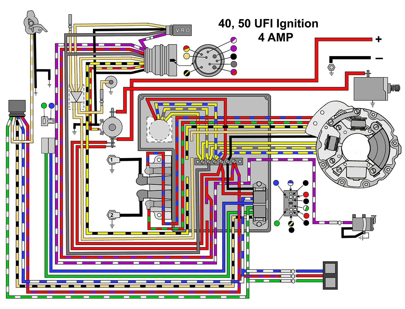
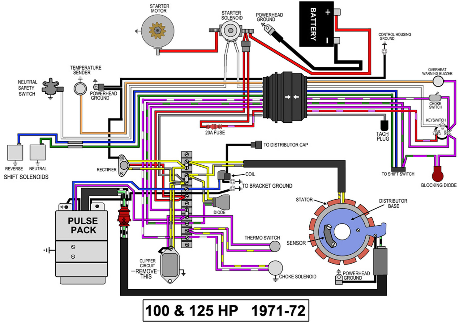
When it comes to working on Evinrude outboard motors, understanding the Evinrude Ignition Switch Wiring Diagram is crucial. This diagram provides a visual representation of the electrical connections within the ignition system, helping mechanics troubleshoot issues and make necessary repairs.
Why Evinrude Ignition Switch Wiring Diagrams are essential
1. Provides a visual representation of the ignition system’s wiring connections
2. Helps identify components and their respective functions
3. Facilitates troubleshooting of electrical issues
How to read and interpret Evinrude Ignition Switch Wiring Diagrams effectively
1. Identify key components such as the ignition switch, battery, starter solenoid, and ignition coil
2. Follow the color-coded wires to understand their connections
3. Pay attention to symbols and labels for additional guidance
Using Evinrude Ignition Switch Wiring Diagrams for troubleshooting electrical problems
1. Locate the specific wiring diagram that corresponds to your outboard motor model
2. Trace the electrical path to pinpoint any faulty connections or components
3. Use a multimeter to test continuity and voltage at various points
Importance of safety when working with electrical systems
1. Always disconnect the battery before working on the ignition system
2. Wear appropriate protective gear such as gloves and safety glasses
3. Double-check all connections before reapplying power to the system
- 4. Avoid working on electrical systems in wet or damp conditions
- 5. Seek professional help if you are unsure or uncomfortable with electrical work
Evinrude Ignition Switch Wiring Diagram
Evinrude Ignition Switch Wiring Diagram – Easy Wiring

Evinrude E-tec Ignition Switch Wiring Diagram

Brp Evinrude Ignition Switch Wiring Diagram

Evinrude Ignition Switch Wiring Diagram

EVINRUDE JOHNSON Outboard Wiring Diagrams — MASTERTECH MARINE

Evinrude Ignition Switch Wiring Diagram Database
