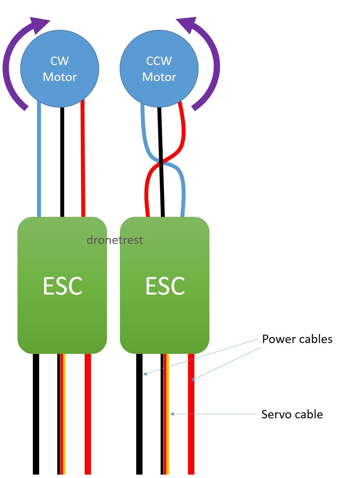
When it comes to understanding the electrical system of a vehicle, an Esc Wiring Diagram is an invaluable tool. This diagram shows the wiring connections for the Electronic Speed Controller (ESC) in a vehicle, which is responsible for controlling the speed of the electric motor. By studying the Esc Wiring Diagram, mechanics and enthusiasts can gain a better understanding of how the electrical components are connected and how they interact with each other.
Importance of Esc Wiring Diagrams
Esc Wiring Diagrams are essential for several reasons:
- They provide a visual representation of the wiring connections, making it easier to identify components and troubleshoot issues.
- They help ensure proper installation and connection of electrical components, reducing the risk of errors and malfunctions.
- They serve as a reference guide for future maintenance and repairs, allowing mechanics to quickly locate and inspect specific wiring connections.
Reading and Interpreting Esc Wiring Diagrams
Reading and interpreting Esc Wiring Diagrams can seem daunting at first, but with some practice and guidance, it becomes much easier:
- Start by identifying the key components and connections on the diagram, such as the ESC unit, battery, motor, and various wires.
- Follow the flow of the wiring connections from one component to another, paying attention to the direction of the arrows and symbols used.
- Refer to the legend or key provided with the diagram to understand the meaning of different symbols and colors used.
Using Esc Wiring Diagrams for Troubleshooting
Esc Wiring Diagrams are a valuable tool for troubleshooting electrical problems in a vehicle:
- By comparing the wiring connections in the diagram to the actual components in the vehicle, mechanics can pinpoint the source of an electrical issue.
- They can help identify faulty connections, damaged wires, or incorrect installations that may be causing the problem.
- Following the wiring diagram step by step can guide mechanics through the troubleshooting process, ensuring a systematic approach to finding and fixing the issue.
Safety Tips and Best Practices
Working with electrical systems and wiring diagrams requires caution and adherence to safety protocols:
- Always disconnect the battery before working on any electrical components to prevent the risk of electrical shock or short circuits.
- Use insulated tools and wear protective gear, such as gloves and safety goggles, to protect yourself from electrical hazards.
- Double-check your connections and follow the wiring diagram carefully to avoid mistakes that could lead to damage or injury.
Esc Wiring Diagram
AIKON SEFM 30A 4-IN-1 ESC Anschlussplan / Wiringplan

Basic ESC | Blue Robotics

A Comprehensive Guide to Understanding Esc Wiring Diagrams

Innovatehouston Tech: Bec Esc Wiring Diagram

ESC to motor connection guide – how to reverse your motor direction the

100A/200A 4-20S Brushless ESC Controller for Dual Motor | Brushless.com
