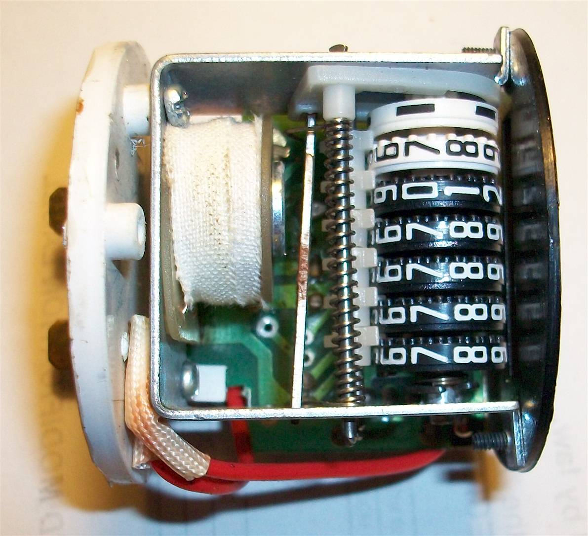
Engine Hour Meter Wiring Diagrams are essential tools for mechanics and technicians to understand the electrical systems in engines. These diagrams provide a visual representation of the wiring connections and components in an engine, helping users troubleshoot electrical issues and perform maintenance tasks efficiently.
Why Engine Hour Meter Wiring Diagrams are Essential
- Helps identify wire colors and connections
- Aids in understanding the electrical layout of the engine
- Facilitates troubleshooting of electrical problems
- Ensures proper installation of new components
Reading and Interpreting Engine Hour Meter Wiring Diagrams
When reading an Engine Hour Meter Wiring Diagram, it’s important to familiarize yourself with the symbols and abbreviations used in the diagram. Each wire color and component is represented by a specific symbol, making it easier to follow the wiring connections. Additionally, pay attention to the legend or key that explains the symbols used in the diagram.
Using Engine Hour Meter Wiring Diagrams for Troubleshooting
- Identify the specific electrical component or circuit in question
- Trace the wiring connections to pinpoint any issues or faults
- Compare the actual wiring with the diagram to identify discrepancies
- Use a multimeter to test for continuity and voltage at different points in the circuit
Importance of Safety
When working with electrical systems and using wiring diagrams, it’s crucial to prioritize safety to prevent accidents and injuries. Here are some safety tips and best practices to follow:
- Always disconnect the battery before working on the electrical system
- Use insulated tools to avoid electrical shocks
- Avoid working on live circuits whenever possible
- Follow proper lockout/tagout procedures when working on energized circuits
Engine Hour Meter Wiring Diagram
Hour meter wiring | Weekend Freedom Machines
Engine Hour Meter Wiring Diagram

13+ engine hour meter wiring diagram – DiklaYakoot

Yanmar 3gm30f Wiring Diagram – Wiring Diagram

Enm Hour Meter Wiring – Wiring Diagram Pictures

Quartz Hour Meter Wiring Diagram – Coearth
