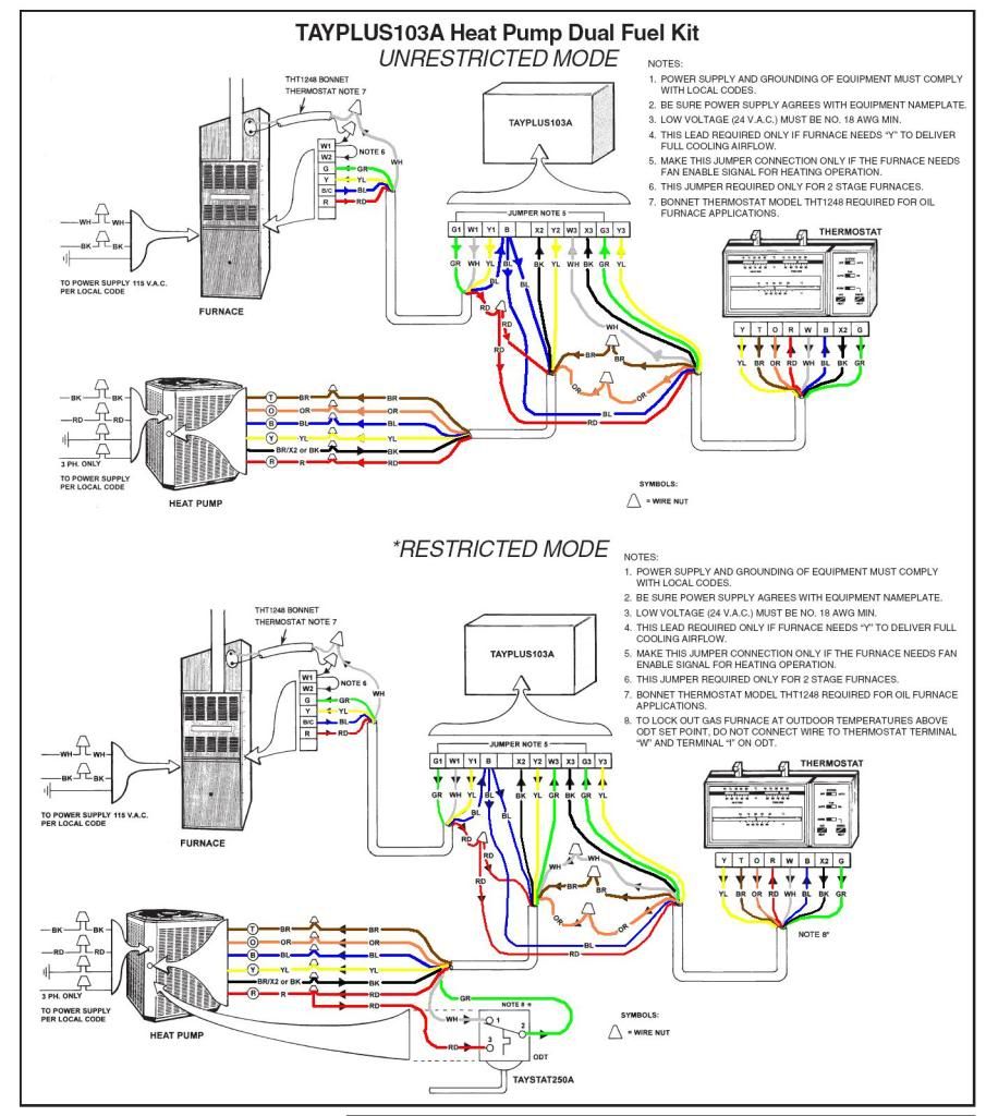
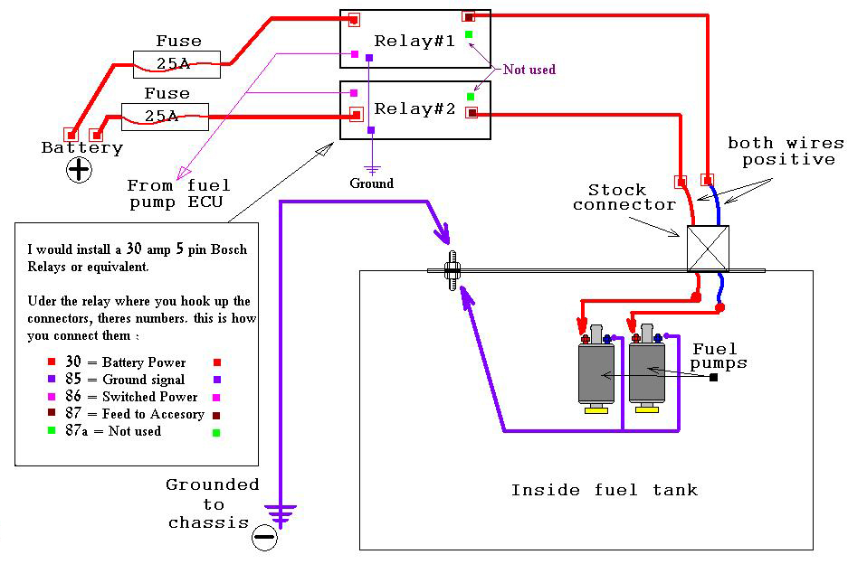
Understanding the Dual Fuel Heat Pump Wiring Diagram is crucial for anyone working with HVAC systems. This diagram provides a visual representation of the electrical connections and components within the heat pump system, helping technicians troubleshoot issues, install new equipment, or make repairs.
Why Dual Fuel Heat Pump Wiring Diagrams are essential
- Ensure proper installation of equipment
- Identify and troubleshoot electrical issues
- Follow safety guidelines
How to read and interpret Dual Fuel Heat Pump Wiring Diagrams
When looking at a wiring diagram, it’s important to understand the symbols and color codes used to represent different components and connections. Refer to the legend or key provided on the diagram to decipher the information accurately. Pay close attention to the layout and sequence of wires to ensure correct installation and operation.
Using Dual Fuel Heat Pump Wiring Diagrams for troubleshooting
When facing electrical problems with a heat pump system, the wiring diagram is a valuable tool for pinpointing the source of the issue. By tracing the electrical flow and checking for continuity, technicians can identify faulty components, loose connections, or damaged wires. This information helps streamline the troubleshooting process and ensures efficient repairs.
Safety tips when working with electrical systems
- Always turn off power before working on any electrical equipment
- Use insulated tools to prevent electric shock
- Wear appropriate protective gear, such as gloves and goggles
- Double-check connections before restoring power to the system
Dual Fuel Heat Pump Wiring Diagram
Dual fuel heat pumps: advancing beneficial electrification

Dual Fuel Heat Pump Wiring – Craftsive

Dual pump setup – Advice on wiring

Dual Fuel Heat Pump Wiring Diagram

How to Wire a Dual Fuel Heat Pump? – X Heat Pump

Efficient Heating: Duel-Fuel Heat Pump (DIY) | Family Handyman
