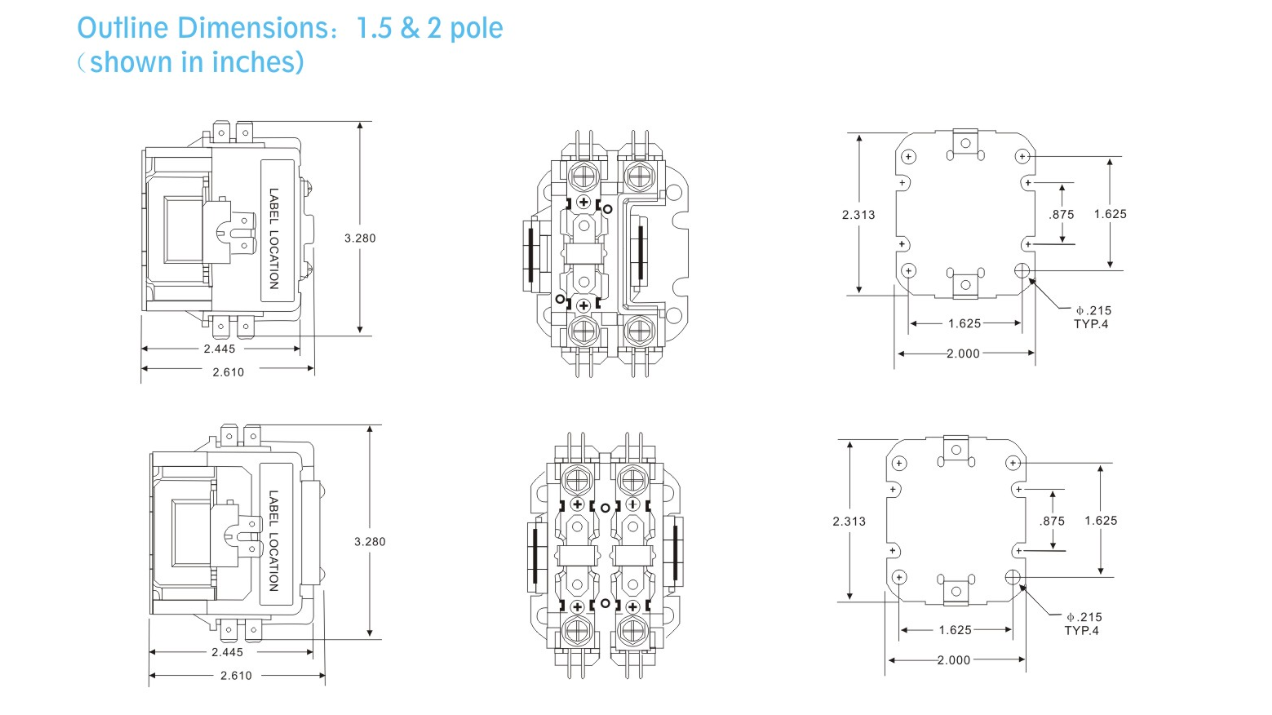
Definite Purpose Contactor Wiring Diagram
When it comes to understanding and working with electrical systems, having a clear and detailed wiring diagram is essential. A Definite Purpose Contactor Wiring Diagram is a visual representation of the electrical connections and components involved in a contactor circuit. This diagram is crucial for electricians, technicians, and even DIY enthusiasts to ensure proper installation and troubleshooting of contactor systems.
Importance of Definite Purpose Contactor Wiring Diagram
- Helps in understanding the connections between different components in the contactor system.
- Ensures proper installation and wiring of the contactor, preventing potential electrical hazards.
- Serves as a reference guide for troubleshooting electrical problems in the contactor system.
- Assists in identifying faulty components or connections in the contactor circuit.
Reading and Interpreting Definite Purpose Contactor Wiring Diagram
When looking at a Definite Purpose Contactor Wiring Diagram, it’s essential to understand the symbols and conventions used in the diagram. Here are some key points to keep in mind:
- Identify the contactor terminals and their corresponding connections in the diagram.
- Follow the wiring paths from the power source to the load to ensure proper circuit configuration.
- Pay attention to the colors and labels of the wires to avoid confusion during installation.
- Refer to the legend or key provided in the diagram for any symbols or abbreviations used.
Using Definite Purpose Contactor Wiring Diagram for Troubleshooting
Definite Purpose Contactor Wiring Diagrams are invaluable tools for troubleshooting electrical problems in contactor systems. Here’s how you can effectively utilize the diagram for troubleshooting:
- Trace the wiring connections to identify any loose or faulty connections in the circuit.
- Check for continuity using a multimeter to ensure proper electrical flow through the contactor.
- Refer to the wiring diagram to pinpoint the location of potential faults or malfunctions in the system.
- Familiarize yourself with the wiring layout to quickly diagnose and resolve issues in the contactor circuit.
Remember, safety should always be a top priority when working with electrical systems and wiring diagrams. Here are some safety tips to keep in mind:
- Always turn off the power supply before working on any electrical circuit.
- Use insulated tools and equipment to prevent electric shock.
- Double-check all connections before energizing the circuit to avoid short circuits.
- Seek professional help if you’re unsure about any aspect of the wiring or troubleshooting process.
Definite Purpose Contactor Wiring Diagram
Understanding The Basics Of 240 Volt Contactor Wiring Diagrams – WIREGRAM

24 Volt Contactor Wiring Diagram – Esquilo.io

How to Wire a Contactor: 8 Steps (with Pictures) – wikiHow

Contactor Wiring Diagram For 3 Phase Motor with Overload relay
SA SERIES Definite Purpose Contactor – 2 POLE – SA-2P-40A-24V – HeCheng

2 Pole Lighting Contactor Wiring Diagram
