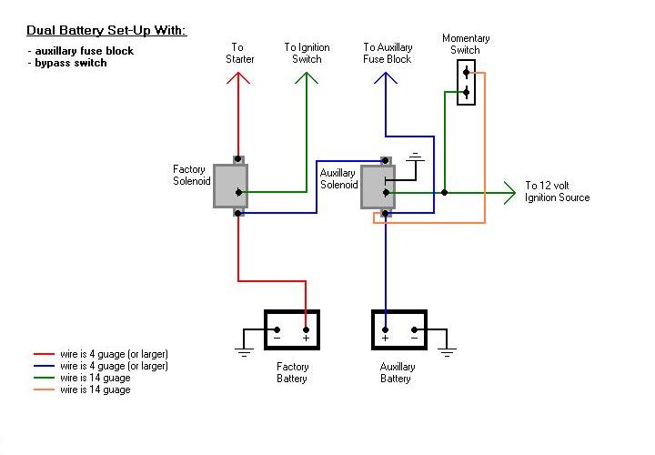
Continuous Duty Solenoid Wiring Diagrams are essential tools for understanding the electrical connections and functions of continuous duty solenoids. These diagrams provide a visual representation of how the various components of the solenoid are connected and interact with each other. By studying these diagrams, mechanics and technicians can troubleshoot electrical issues, make repairs, or install new solenoids with confidence.
Importance of Continuous Duty Solenoid Wiring Diagrams
- Helps in understanding the electrical connections of the solenoid
- Aids in troubleshooting electrical issues
- Ensures proper installation of new solenoids
Reading and Interpreting Continuous Duty Solenoid Wiring Diagrams
Continuous Duty Solenoid Wiring Diagrams typically consist of lines and symbols that represent the various components and connections within the solenoid circuit. By following the lines and understanding the symbols, one can determine how the solenoid is wired and how electricity flows through it. It is important to pay attention to the legends and color codes used in the diagram to accurately interpret the information presented.
Using Continuous Duty Solenoid Wiring Diagrams for Troubleshooting
When faced with electrical problems in a continuous duty solenoid, referring to the wiring diagram can help pinpoint the source of the issue. By following the wiring paths and checking for continuity or voltage at various points, technicians can identify faulty connections, damaged components, or other issues that may be causing the malfunction. This information can then be used to make the necessary repairs or replacements to restore the solenoid to proper working condition.
Safety Tips for Working with Continuous Duty Solenoid Wiring Diagrams
- Always disconnect the power source before working on any electrical system
- Use insulated tools when handling live wires to prevent electric shock
- Double-check your connections and wiring before applying power to the system
- If unsure about any aspect of the wiring diagram or electrical system, consult a professional technician
Continuous Duty Solenoid Wiring Diagram
Continuous Duty Solenoid Wiring Diagram – Artled

Cole Hersee Continuous Duty Solenoid Wiring Diagram – Herbally

Cole Hersee Continuous Duty Solenoid Wiring Diagram – Wiring Digital
Cole Hersee Continuous Duty Solenoid Wiring Diagram » Wiring Digital
12 Volt Continuous Duty Solenoid Wiring Diagram » Wiring Digital And

12 Volt Continuous Duty Solenoid Wiring Diagram
