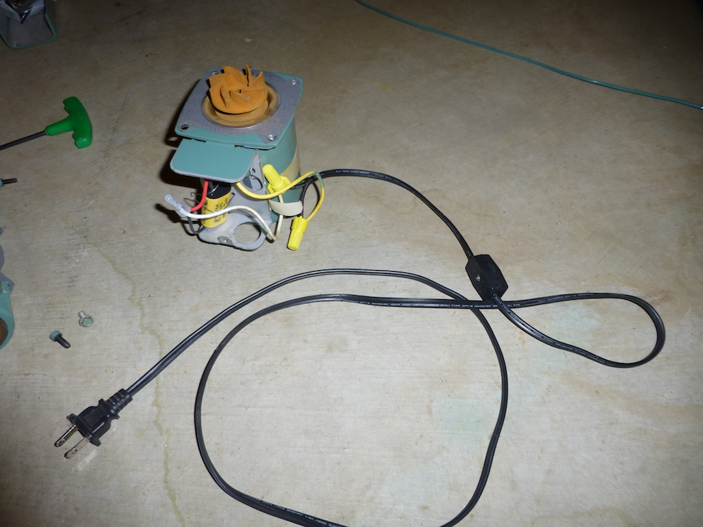
Circulator Pump Wiring Diagram
When it comes to understanding the electrical system of a circulator pump, a wiring diagram is an essential tool. Circulator pump wiring diagrams provide a visual representation of the electrical connections within the pump, helping technicians troubleshoot issues and make necessary repairs.
Importance of Circulator Pump Wiring Diagram
Here are some reasons why circulator pump wiring diagrams are essential:
- Helps identify the different components of the pump
- Shows the electrical connections between components
- Aids in diagnosing electrical issues
- Ensures proper installation and maintenance
Reading and Interpreting Circulator Pump Wiring Diagram
Reading and interpreting a circulator pump wiring diagram can be daunting for some, but with the right approach, it becomes much easier:
- Start by familiarizing yourself with the key symbols and color codes used in the diagram
- Follow the flow of the electrical current through the diagram to understand the circuit
- Identify the power source, switches, relays, and other components
- Refer to the manufacturer’s guide for specific details about the wiring diagram
Using Circulator Pump Wiring Diagram for Troubleshooting
When faced with electrical problems in a circulator pump, the wiring diagram is your best friend. Here’s how you can use it for troubleshooting:
- Check for loose connections or damaged wires indicated in the diagram
- Trace the flow of electricity to locate the source of the problem
- Compare the actual wiring with the diagram to spot any discrepancies
- Consult with a professional if you’re unsure about the interpretation of the diagram
Safety Tips
Working with electrical systems can be dangerous, so it’s crucial to prioritize safety when using wiring diagrams:
- Always turn off the power before working on the circulator pump
- Use insulated tools to prevent electrical shocks
- Wear appropriate safety gear, such as gloves and goggles
- Double-check your work and seek help if you’re unsure about any step
Circulator Pump Wiring Diagram
Taco Circulator Pump Wiring Diagram

38 taco circulator pump wiring diagram

36+ taco circulator pump wiring diagram – CherinaGraeme

Taco Circulator Pump Wiring Diagram – Easy Wiring

Taco Circulating Pump Installation Diagram – diagramwirings

Taco 007 Circulator Pump Wiring Diagram Taco 006 B4 Wiring Diagram Taco
