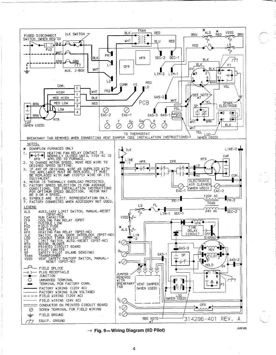
When it comes to understanding the intricate electrical systems in HVAC units, having a clear and concise Carrier Wiring Diagram can make all the difference. These diagrams provide a visual representation of the wiring and electrical components in a Carrier system, helping technicians troubleshoot issues and make necessary repairs.
Why Carrier Wiring Diagrams are Essential
Carrier Wiring Diagrams are essential for several reasons:
- They provide a detailed overview of the electrical components in a Carrier system.
- They help technicians identify connections and troubleshoot electrical issues quickly and accurately.
- They serve as a guide for proper installation and maintenance of Carrier units.
Reading and Interpreting Carrier Wiring Diagrams
Reading and interpreting Carrier Wiring Diagrams may seem daunting at first, but with the right approach, it can be a straightforward process:
- Start by familiarizing yourself with the symbols and abbreviations used in the diagram.
- Follow the flow of the diagram from the power source to the various components in the system.
- Pay attention to color codes and labels to ensure proper connections.
Using Carrier Wiring Diagrams for Troubleshooting
Carrier Wiring Diagrams are invaluable tools for troubleshooting electrical problems in HVAC units:
- Identify the specific circuit or component causing the issue on the diagram.
- Trace the wiring to locate any loose connections, damaged wires, or faulty components.
- Refer to the diagram to determine the appropriate voltage and resistance readings for testing.
Importance of Safety
Working with electrical systems can be dangerous, so it’s crucial to prioritize safety at all times:
- Always turn off the power supply before working on any electrical components.
- Use insulated tools and equipment to prevent electric shock.
- Wear appropriate personal protective equipment, such as gloves and safety goggles.
- Follow proper safety procedures and guidelines when handling wiring and electrical components.
Carrier Wiring Diagram
Fig. 13 — typical single-phase wiring diagram | Carrier 48NLT User

Carrier Economizer Wiring Diagram

Carrier Wiring Diagram

Carrier Wiring Diagram / Fig. 9—wiring diagram (iid pilot) | Carrier

Carrier Wiring Diagram / Fig. 9—wiring diagram (iid pilot) | Carrier

Carrier Tstatccprh01 B Wiring Diagram – Chicic
