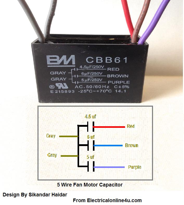
When it comes to electrical systems, a Capacitor Wiring Diagram is an essential tool for understanding the connections and circuits within a capacitor. This diagram provides a visual representation of how the capacitor is wired, helping technicians troubleshoot electrical issues and ensure proper installation.
Why Capacitor Wiring Diagrams are Essential
Capacitor Wiring Diagrams are crucial for several reasons:
- They show the exact wiring connections of the capacitor, ensuring correct installation.
- They help identify faulty connections or components that may be causing electrical issues.
- They provide a roadmap for understanding the electrical circuit and how the capacitor interacts with other components.
How to Read and Interpret Capacitor Wiring Diagrams
Reading and interpreting a Capacitor Wiring Diagram can seem daunting at first, but with a little guidance, it becomes much easier:
- Start by identifying the main components of the diagram, such as the capacitor, terminals, and connections.
- Follow the lines and symbols to trace the wiring connections between components.
- Refer to the diagram’s key or legend to understand what each symbol represents.
Using Capacitor Wiring Diagrams for Troubleshooting
Capacitor Wiring Diagrams are an invaluable tool when troubleshooting electrical problems:
- They help pinpoint the location of faulty wiring or connections that may be causing issues.
- By following the diagram, technicians can easily identify and replace damaged components.
- Using the diagram, technicians can test the capacitor and other components to ensure they are functioning properly.
Importance of Safety
Working with electrical systems can be dangerous, so it’s crucial to prioritize safety when using Capacitor Wiring Diagrams:
- Always turn off the power supply before working on any electrical components.
- Use insulated tools and equipment to prevent electric shock.
- Double-check all connections before powering up the system to avoid short circuits or electrical fires.
Capacitor Wiring Diagram
AC Capacitor Wiring Diagram and Connection Procedure – ETechnoG

Bm Cbb61 Capacitor Wiring Diagram – Timesked

Capacitor Compressor Wiring Diagram Single Phase

Ac Capacitor Wiring Diagram

Wiring Diagram For Capacitor Run Motor – Wiring Diagram

Capacitor Compressor Wiring Diagram Single Phase
