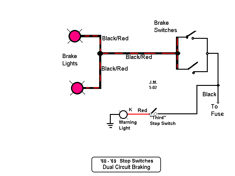
When it comes to ensuring the safety and functionality of your vehicle, understanding the Brake Light Switch Wiring Diagram is essential. This diagram provides a detailed outline of how the brake light switch is wired into your vehicle’s electrical system, helping you troubleshoot any issues that may arise.
Why Brake Light Switch Wiring Diagram are Essential
The Brake Light Switch Wiring Diagram is crucial for several reasons:
- It helps you understand the wiring connections for the brake light switch.
- It allows you to identify any potential issues with the wiring that may be causing brake light malfunctions.
- It provides a roadmap for making repairs or modifications to the brake light system.
Reading and Interpreting Brake Light Switch Wiring Diagram
When looking at a Brake Light Switch Wiring Diagram, it’s important to pay attention to the following:
- The color-coding of the wires to ensure they are connected correctly.
- The symbols used to represent different components in the wiring diagram.
- The direction of the current flow to understand how the circuit is connected.
Using Brake Light Switch Wiring Diagram for Troubleshooting
Brake Light Switch Wiring Diagrams are invaluable for troubleshooting electrical problems in your vehicle. By following the diagram, you can:
- Identify any loose or damaged connections that may be causing the issue.
- Test the continuity of the wires to ensure there are no breaks in the circuit.
- Trace the wiring back to the source of the problem for a quick and effective repair.
Importance of Safety
Working with electrical systems can be dangerous if proper precautions are not taken. When using Brake Light Switch Wiring Diagrams, remember to:
- Always disconnect the battery before working on any electrical components.
- Use insulated tools to prevent electrical shocks.
- Double-check all connections before reassembling the system to avoid any short circuits.
Brake Light Switch Wiring Diagram
Brake Light Switch Circuit Wiring Diagram

The Ultimate Guide: E36 Brake Light Switch Wiring Diagram

Brake Light Circuit Diagram

Basic Brake Light Switch Wiring Diagram Collection

2000 Chevy Silverado Brake Light Switch Wiring Diagram – Wiring Site

Basic Brake Light Switch Wiring Diagram
