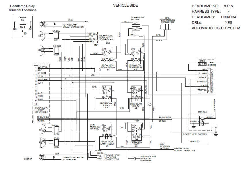
When it comes to understanding the intricacies of your Boss V Plow, having a comprehensive wiring diagram is essential. The Boss V Plow Wiring Diagram serves as a roadmap for the electrical system of your plow, helping you understand how all the components are connected and ensuring that everything is functioning properly.
Why Boss V Plow Wiring Diagrams are Essential
Understanding the wiring diagram for your Boss V Plow is crucial for a variety of reasons:
- Ensures proper installation of the plow
- Helps in troubleshooting electrical issues
- Provides a visual representation of the electrical system
- Ensures safety when working with electrical components
How to Read and Interpret Boss V Plow Wiring Diagrams
Reading and interpreting a Boss V Plow Wiring Diagram may seem daunting at first, but with a little guidance, it becomes much easier:
- Identify the key components in the diagram
- Understand the symbols and color codes used
- Follow the flow of the electrical current
- Refer to the legend for any clarification
Using Boss V Plow Wiring Diagrams for Troubleshooting
When faced with electrical problems with your Boss V Plow, the wiring diagram can be a valuable tool for troubleshooting:
- Identify the specific circuit that is causing the issue
- Check for any breaks or shorts in the wiring
- Verify the connections and components in the affected circuit
- Refer to the diagram to pinpoint the source of the problem
Importance of Safety
Working with electrical systems can be dangerous, so it’s important to prioritize safety when using wiring diagrams:
- Always disconnect the power source before working on the electrical system
- Use insulated tools to avoid electric shocks
- Double-check all connections before powering up the system
- If in doubt, consult a professional mechanic or electrician
Boss V Plow Wiring Diagram
Schematic Boss V Plow Wiring Diagram Database

Boss V Plow Parts Diagram – General Wiring Diagram

Boss V Plow Solenoid Wiring Diagram – Esquilo.io

Understanding The Boss V Plow Solenoid Wiring Diagram – Wiring Diagram

Wiring Diagram For Boss Snow Plow: How To Install And Troubleshoot
