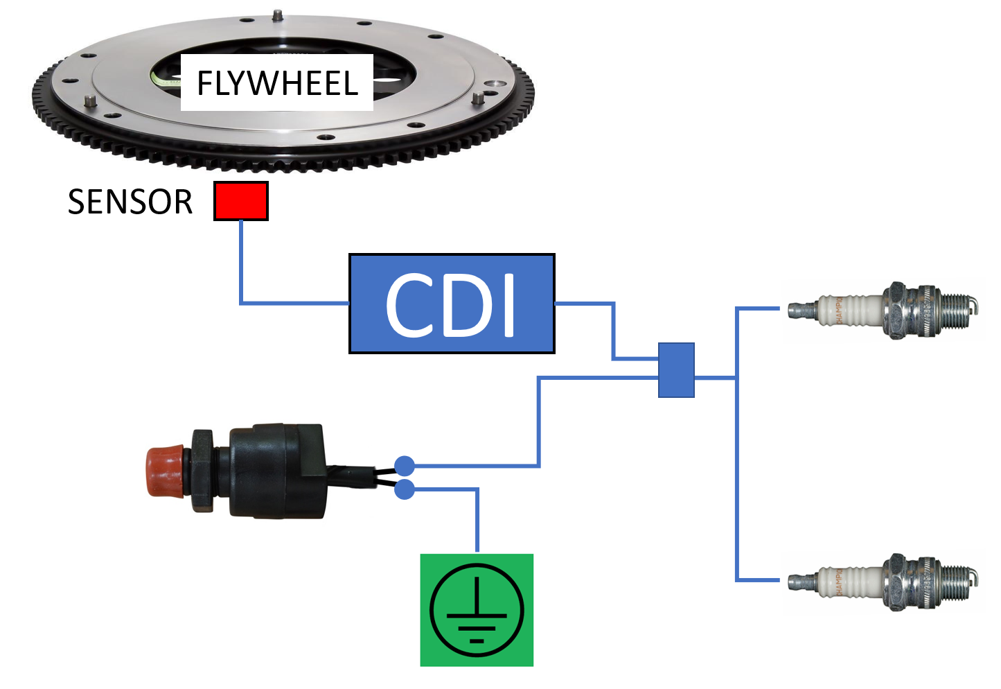
Boat Kill Switch Wiring Diagrams are crucial components for ensuring the safety and functionality of a boat’s electrical system. These diagrams provide a detailed illustration of how the kill switch is wired into the boat’s electrical system, allowing boat owners to understand the connections and troubleshoot any issues that may arise.
Why Boat Kill Switch Wiring Diagrams are Essential
Boat Kill Switch Wiring Diagrams are essential for the following reasons:
- Ensure proper installation of the kill switch
- Help diagnose electrical issues efficiently
- Provide a reference for future maintenance and repairs
Reading and Interpreting Boat Kill Switch Wiring Diagrams
When reading a Boat Kill Switch Wiring Diagram, it is important to pay attention to the following:
- Identify the components and their connections
- Understand the flow of electricity through the system
- Follow the wiring color codes for accurate connections
Using Boat Kill Switch Wiring Diagrams for Troubleshooting
Boat Kill Switch Wiring Diagrams can be used for troubleshooting electrical problems by:
- Locating the source of the issue within the wiring system
- Checking for loose or damaged connections
- Testing the continuity of the kill switch circuit
Importance of Safety
When working with Boat Kill Switch Wiring Diagrams, it is crucial to prioritize safety. Follow these safety tips and best practices:
- Always disconnect the boat’s battery before working on the electrical system
- Use insulated tools to prevent electrical shocks
- Avoid working in wet or damp conditions to prevent accidents
Boat Kill Switch Wiring Diagram
How To Fit A Kill-Switch | Boat Fittings

How to Install and Wire a Boat Kill Switch: A Step-by-Step Guide

How To Fit A Kill-Switch | Boat Fittings

Wiring Diagram For Boat Kill Switch – Wiring Diagram and Schematics
Wiring Diagram For Seadog Safety Kill Switch

Marine Kill Switch Wiring Diagram – Wiring Draw And Schematic
