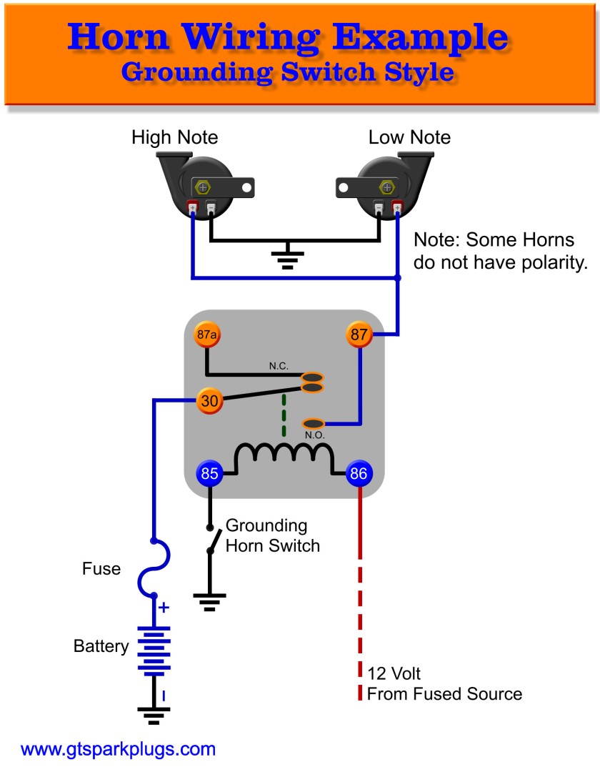
Basic Push Button Horn Wiring Diagrams are essential tools for anyone working with automotive electrical systems. These diagrams provide a visual representation of how the wiring for a push button horn is set up, making it easier to understand and troubleshoot any issues that may arise.
Why are Basic Push Button Horn Wiring Diagrams essential?
- Helps understand the wiring connections for the push button horn
- Allows for easy troubleshooting of electrical issues
- Ensures proper installation of the push button horn
Reading and interpreting Basic Push Button Horn Wiring Diagrams
When looking at a Basic Push Button Horn Wiring Diagram, it’s important to pay attention to the symbols and color codes used. Here are some key points to remember:
- Identify the components: Locate the push button, horn, relay, fuse, and wires in the diagram
- Follow the wiring paths: Trace the lines connecting the components to understand how they are connected
- Understand the symbols: Familiarize yourself with the symbols used for each component in the diagram
Using Basic Push Button Horn Wiring Diagrams for troubleshooting
When faced with electrical problems related to the push button horn, a wiring diagram can be a valuable tool. Here’s how you can use it effectively:
- Check for any loose or disconnected wires indicated in the diagram
- Test the continuity of the wires using a multimeter to ensure proper connections
- Refer to the diagram to identify any faulty components that may need replacement
Safety tips when working with Basic Push Button Horn Wiring Diagrams
Working with electrical systems can be dangerous if proper precautions are not taken. Here are some safety tips to keep in mind:
- Always disconnect the battery before working on any electrical components
- Avoid working on wet surfaces or in damp conditions to prevent electrical shocks
- Use insulated tools when handling wires to avoid short circuits
- Double-check all connections before re-connecting the battery to prevent any mishaps
Basic Push Button Horn Wiring Diagram
Wiring factory horns to a push button | NC4x4

Horn Switch Wiring – Schema Wiring Diagram – Horn Wiring Diagram

19mm Stainless Steel Push Button 5-Pin ON/OFF | MGI SpeedWare

Push Button Horn Wiring Diagram For Your Needs
Car Horn Wiring Diagram – Easy Wiring

Ooga Horn Relay Wiring Diagram
