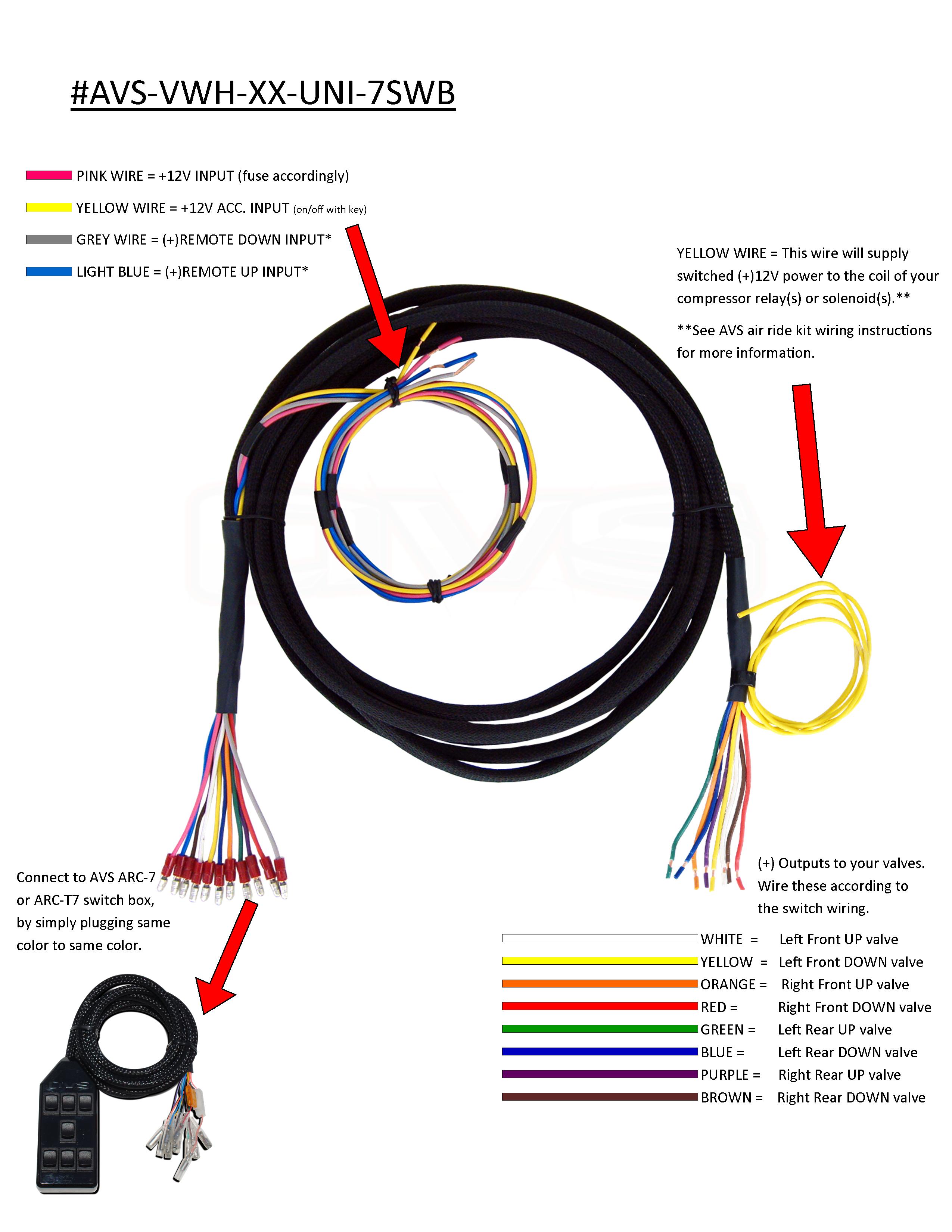
When it comes to customizing vehicles with an air ride suspension system, understanding the Air Ride Switch Box Wiring Diagram is crucial. This diagram outlines the electrical connections for the switch box, allowing you to control the air ride system effectively.
Why Air Ride Switch Box Wiring Diagram are essential
Having a clear understanding of the Air Ride Switch Box Wiring Diagram is essential for the following reasons:
- Ensures proper installation of the switch box
- Helps in troubleshooting electrical issues
- Allows for customization and modifications
How to read and interpret Air Ride Switch Box Wiring Diagram
Reading and interpreting the Air Ride Switch Box Wiring Diagram can be daunting at first, but with a few key tips, you can navigate through it effectively:
- Identify the components and their connections
- Understand the symbols used in the diagram
- Follow the flow of the electrical connections
Using Air Ride Switch Box Wiring Diagram for troubleshooting
When faced with electrical problems in your air ride system, the Wiring Diagram can be a valuable tool for troubleshooting. Here’s how you can use it effectively:
- Locate the problem area in the diagram
- Check for loose connections or damaged wires
- Refer to the diagram to identify potential causes of the issue
Importance of safety
Working with electrical systems can be dangerous if proper precautions are not taken. Here are some safety tips to keep in mind when using Air Ride Switch Box Wiring Diagram:
- Always disconnect the power source before working on the electrical system
- Use insulated tools to prevent shock hazards
- Double-check your connections to ensure they are secure and correct
Air Ride Switch Box Wiring Diagram
Air Ride Switch Box Wiring Diagram

Air Ride Switch Wiring Diagram

️Air Ride Compressor Wiring Diagram Free Download| Gmbar.co

Avs 3 Switch Box Wiring Diagram – Wiring Diagram

air ride switch box wiring diagram – JedwigaRomy
