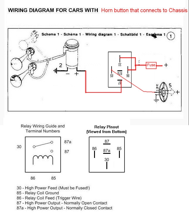
Air Horn Relay Wiring Diagram
When it comes to installing air horns in your vehicle, understanding the Air Horn Relay Wiring Diagram is crucial. This diagram provides a detailed layout of how the relay, wiring, and electrical components are connected to ensure the air horns function properly.
Importance of Air Horn Relay Wiring Diagram
- Ensures proper installation of air horns
- Prevents electrical issues and short circuits
- Helps troubleshoot any problems that may arise
- Ensures safety while working with electrical systems
Reading and Interpreting the Diagram
Reading and interpreting the Air Horn Relay Wiring Diagram can seem daunting at first, but with a little guidance, it becomes much easier. Here are some key points to keep in mind:
- Identify the components: Relays, wiring, fuses, and switches
- Understand the symbols and color codes used in the diagram
- Follow the flow of current from the power source to the air horns
Using Diagrams for Troubleshooting
Air Horn Relay Wiring Diagrams are not only useful for installation but also for troubleshooting electrical problems. By following the diagram, you can easily identify any issues such as loose connections, blown fuses, or faulty relays.
Safety Tips for Working with Electrical Systems
- Always disconnect the battery before working on any electrical components
- Use insulated tools to prevent electric shocks
- Avoid working on wet surfaces or in damp conditions
- Double-check all connections before testing the air horns
By following the Air Horn Relay Wiring Diagram and adhering to safety precautions, you can successfully install and troubleshoot air horns in your vehicle without any issues. Remember, safety always comes first when working with electrical systems.
Air Horn Relay Wiring Diagram
Air Horn Wiring Diagram With Relay

Air Horn Relay Wiring Diagram – Diysive

How to Wire a Horn Relay (5-Step Guide)

Bosch Air Horn Wiring

Horn Relay Wiring Diagram | Wiring Diagram

HORN RELAY simple wiring – YouTube
