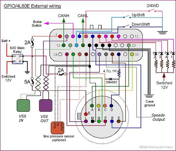
4l80e Speed Sensor Wiring Diagram is an essential tool for understanding the electrical connections in a vehicle’s transmission system. These diagrams provide a detailed overview of how the speed sensor wiring is connected, helping mechanics diagnose and repair issues effectively.
Why are 4l80e Speed Sensor Wiring Diagrams Essential?
- Help identify the exact location of the speed sensor wiring in the transmission system.
- Provide a clear visual representation of the wiring connections, making it easier to troubleshoot any issues.
- Aid in understanding the circuitry and flow of electrical signals within the transmission system.
- Ensure proper installation and maintenance of the speed sensor wiring for optimal performance.
How to Read and Interpret 4l80e Speed Sensor Wiring Diagrams
Reading and interpreting 4l80e Speed Sensor Wiring Diagrams may seem daunting at first, but with a little guidance, it can be a valuable skill for any mechanic. Here are some tips:
- Start by familiarizing yourself with the key symbols and color codes used in the diagram.
- Follow the flow of the wiring connections from the speed sensor to the control module.
- Pay attention to any labels or annotations that provide additional information about the wiring connections.
- Use a multimeter to test the continuity and voltage at various points along the wiring to ensure proper functionality.
Using 4l80e Speed Sensor Wiring Diagrams for Troubleshooting Electrical Problems
4l80e Speed Sensor Wiring Diagrams are invaluable when it comes to troubleshooting electrical issues in a vehicle’s transmission system. Here’s how you can use them effectively:
- Identify any loose or damaged connections in the speed sensor wiring that may be causing the problem.
- Trace the wiring back to the control module to check for any faulty components or incorrect connections.
- Compare the actual wiring in the vehicle to the diagram to pinpoint any discrepancies that may be causing the issue.
- Use the diagram to guide you through the testing and repair process, ensuring that all connections are properly secured and functioning as intended.
Safety Tips and Best Practices
When working with electrical systems and using wiring diagrams, it’s crucial to prioritize safety to prevent any accidents or injuries. Here are some safety tips and best practices to keep in mind:
- Always disconnect the vehicle’s battery before working on any electrical components to avoid the risk of electric shock.
- Use insulated tools and gloves when handling wiring connections to prevent accidental contact with live circuits.
- Avoid working on electrical systems in wet or damp conditions to minimize the risk of short circuits or electrical fires.
- Double-check all connections and wiring before reassembling the vehicle to ensure everything is properly installed and secure.
4l80e Speed Sensor Wiring Diagram
4l80e speed sensors and external wiring info – YouTube

Transzilla—We Install The SuperMatic 4L85-E From Chevrolet Performance

AD0

4L80E Speed Sensor – Bakmakker – Amerikaanse automaatbakken

How to setup a 4L80E/4L85E with FTManager – FuelTech USA

Electronic Transmission Performance By Baumann Electronic Controls
