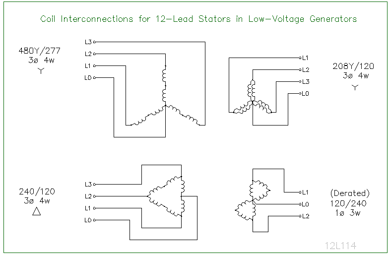
When it comes to understanding and working with electrical systems, having a clear understanding of a 480 Volt 12 Lead Motor Wiring Diagram is crucial. These diagrams provide a detailed map of how the various components of a motor are connected and can help ensure that the motor operates efficiently and safely.
Why are 480 Volt 12 Lead Motor Wiring Diagrams Essential?
1. Ensure proper installation: Wiring diagrams help ensure that the motor is installed correctly, reducing the risk of electrical malfunctions or failures.
2. Aid in troubleshooting: Having a clear wiring diagram can make troubleshooting electrical issues much easier, saving time and effort.
3. Safety: Understanding the wiring diagram can help prevent accidents and injuries when working with electrical systems.
How to Read and Interpret 480 Volt 12 Lead Motor Wiring Diagrams
1. Identify the components: Familiarize yourself with the various symbols and components represented in the diagram.
2. Follow the flow: Start at the power source and follow the path of the wiring to understand how the motor is connected.
3. Note the connections: Pay close attention to how the wires are connected to each component, including any switches or relays.
Using 480 Volt 12 Lead Motor Wiring Diagrams for Troubleshooting
1. Identify potential issues: Look for any loose connections, damaged wires, or incorrect wiring that could be causing the problem.
2. Compare to the actual wiring: Compare the diagram to the actual wiring of the motor to see if there are any discrepancies.
3. Test components: Use a multimeter or other testing tools to check the continuity and voltage of the various components.
Safety should always be a top priority when working with electrical systems. Here are some important safety tips to keep in mind:
- Always turn off the power before working on any electrical system.
- Use insulated tools and wear appropriate safety gear, such as gloves and goggles.
- Double-check your work and have a qualified electrician inspect it before powering up the system.
480 Volt 12 Lead Motor Wiring Diagram
Understanding 480 Volt 3 Phase 12 Lead Motor Wiring Diagram – Moo Wiring

Get 12 Lead 480 Volt Generator Wiring Diagram Background – ktmclubitalia.it

12 Lead 480v Motor Wiring Diagram – Organically

480 Volt 3 Phase 12 Leads Motor Wiring Diagram – Jean puppie
Basic 480 Motor Wiring Diagram | Wiring Library

480 Electric Motor Wiring Diagram 480 Volt Motor Wiring Diagram
