Opening Paragraph:
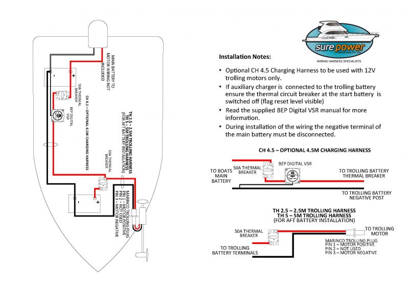
When it comes to ensuring the smooth operation of your trolling motor, understanding the intricacies of a 36 Volt Trolling Motor Wiring Diagram is crucial. These diagrams serve as a roadmap for connecting the various components of your trolling motor system, allowing for optimal performance on the water.
Why are 36 Volt Trolling Motor Wiring Diagrams Essential?
36 Volt Trolling Motor Wiring Diagrams are essential for several reasons:
- They provide a visual representation of how each component in the trolling motor system is connected.
- They help ensure proper wiring and prevent potential electrical issues.
- They serve as a reference point for troubleshooting any problems that may arise.
How to Read and Interpret 36 Volt Trolling Motor Wiring Diagrams
Reading and interpreting 36 Volt Trolling Motor Wiring Diagrams effectively involves:
- Identifying the key components such as batteries, switches, and connectors.
- Following the wiring paths to understand how each component is connected.
- Referencing the diagram when installing new components or troubleshooting issues.
Using 36 Volt Trolling Motor Wiring Diagrams for Troubleshooting Electrical Problems
When faced with electrical problems, 36 Volt Trolling Motor Wiring Diagrams can be a valuable tool for troubleshooting:
- Identifying potential wiring issues such as loose connections or damaged wires.
- Checking the wiring diagram to ensure proper voltage flow through the system.
- Using a multimeter to test for continuity and voltage at various points in the system.
Importance of Safety
Working with electrical systems and wiring diagrams requires a focus on safety. Here are some important safety tips and best practices:
- Always disconnect the battery before working on any electrical components.
- Use insulated tools to prevent electrical shocks.
- Avoid working in wet conditions to prevent the risk of electrocution.
- Follow manufacturer’s guidelines and specifications when making any modifications to the wiring system.
36 Volt Trolling Motor Wiring Diagram
36v Trolling Motor Wiring

36 Volt Series Trolling Motor Connection Kit with On-board Charging

Wiring Diagram For 36 Volt Trolling Motor

36 Volt Trolling Motor Wiring Diagram
36-volt trolling motor wiring diagram – Besttrollingmotor

Minn Kota 36 Volt Trolling Motor Wiring Diagram Database
